Content .. 1135 1136 1137 1138 ..
Toyota Tundra (2015 year). Manual - part 1137
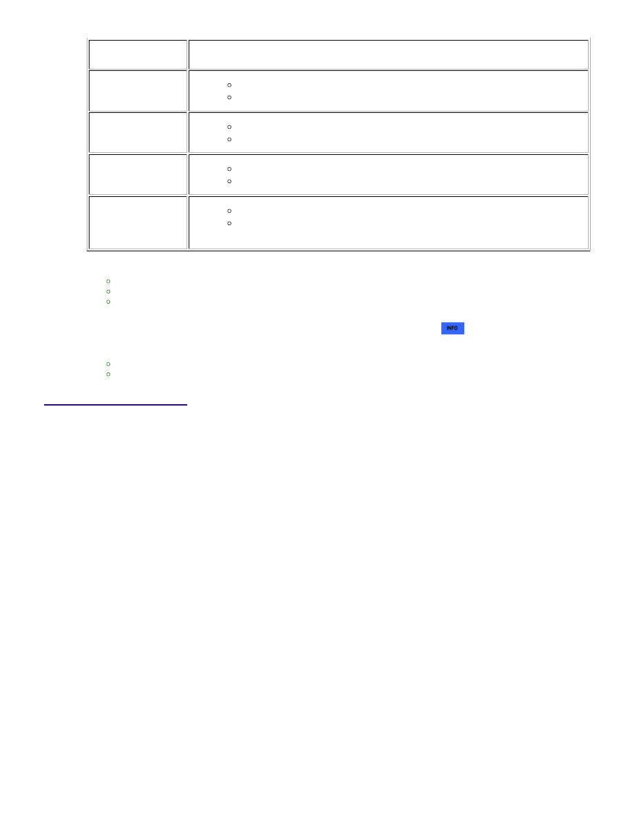
TECHSTREAM
DISPLAY
DESCRIPTION
NORMAL
DTC judgment completed
System normal
ABNORMAL
DTC judgment completed
System abnormal
INCOMPLETE
DTC judgment not completed
Perform driving pattern after confirming DTC enabling conditions
N/A
Unable to perform DTC judgment
HINT:
If the judgment result shows ABNORMAL, the system has a malfunction.
If the judgment result shows NORMAL, the system is normal.
If the judgment result shows INCOMPLETE or N/A, drive the vehicle with the shift lever in S, and then perform
step [C] again.
If no pending DTC is output, perform a universal trip and check for permanent DTCs
.
HINT:
If a permanent DTC is output, the system is malfunctioning.
If no permanent DTC is output, the system is normal.
19.
WIRING DIAGRAM
1UR-FE ENGINE CONTROL SYSTEM: SFI SYSTEM: P0136-P0139,...