Suzuki Grand Vitara JB416 / JB420 / JB419. Manual - part 177


  Index      Suzuki     Suzuki Grand Vitara JB416 / JB420 / JB419 - service repair manual 2007 year


Search            


Content   ..  175  176  177  178   ..


Suzuki Grand Vitara JB416 / JB420 / JB419. Manual - part 177


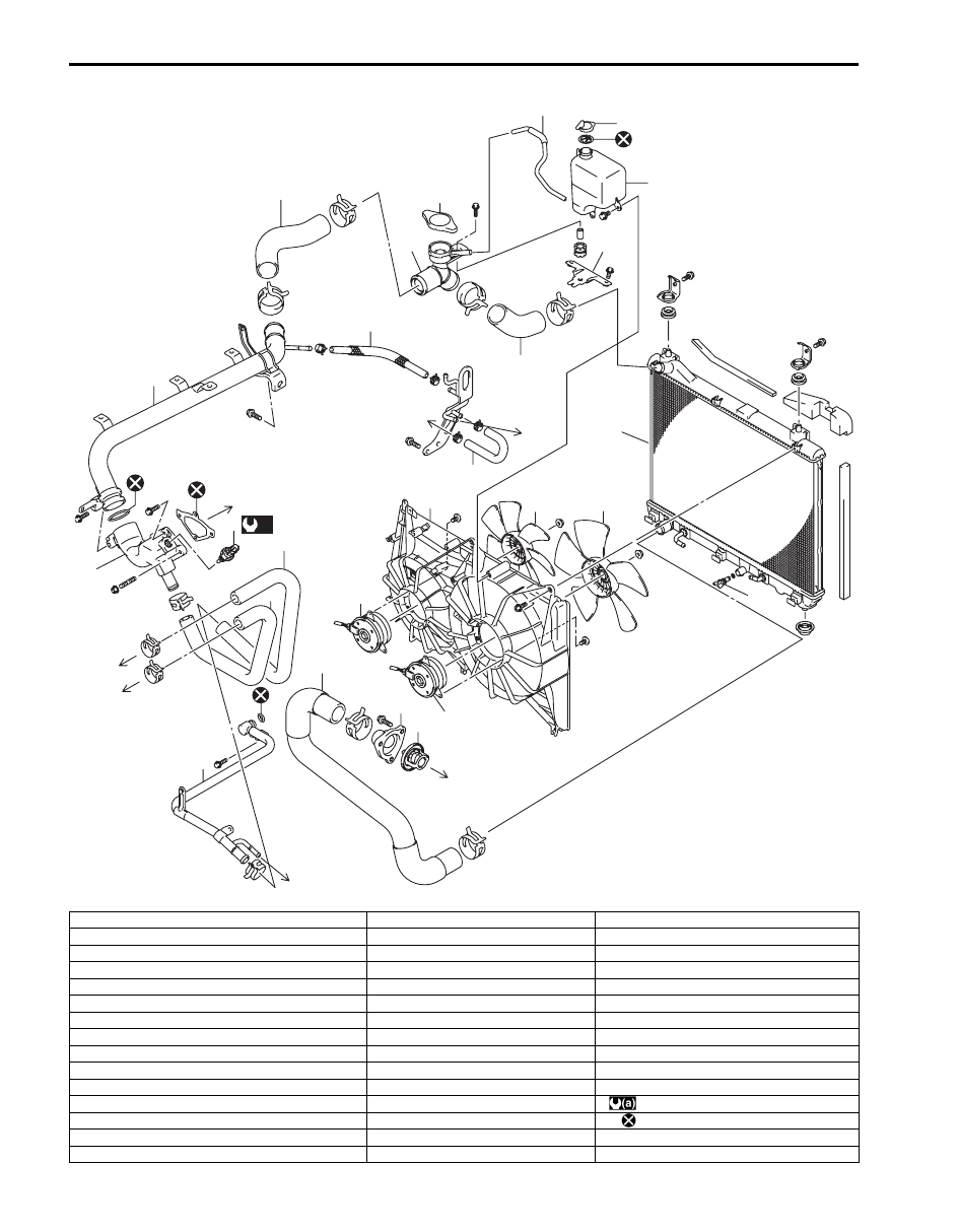
1F-5 Engine Cooling System: For Petrol Engine Model

[B]

8

(a)

21

25

24

15

7

11

6

16

5

33

3

16

14

31

34

29

30

29

32

32

1

4

36

35

37

38

26

2

39

22

23

10

10

9

9

I5JB0A161004-03

[A]: M16 engine model

14. Thermostat

29. To cylinder head

[B]: J20 engine model

15. Thermostat cap

30. To water pump

1. Radiator

16. Radiator inlet No.2 hose

31. To heater core

2. Reservoir

17. Water filler neck

32. To throttle body

3. Radiator cap

18. Water inlet hose

33. Water bypass No.2 hose

4. Drain plug

19. Radiator outlet pipe

34. Water bypass No.1 hose

5. Radiator outlet hose

20. Heater outlet No.2 hose

35. Main fan motor

6. Radiator inlet No.1 hose

21. Heater pipe

36. Sub fan motor

7. Water outlet cap

22. Reservoir hose

37. Sub fan

8. ECT sensor

23. Water filler neck bracket

38. Main fan

9. Gasket

24. Heater inlet hose

39. Reservoir cap

10. O-ring

25. Heater outlet No.1 hose

: 13 N

⋅m (1.3 kgf-m, 9.5 lb-ft)

11. Water outlet pipe

26. Fan shroud

: Do not reuse.

12. Thermostat case water outlet pipe

27. To water filler neck

13. Thermostat case

28. To timing chain cover

Engine Cooling System: For Petrol Engine Model 1F-6

Coolant Level Check

S6JB0A1616002

WARNING

!


To help avoid danger of being burned, do not 
remove radiator cap while engine and 
radiator are still hot. Scalding fluid and steam 
can be blown out under pressure if radiator 
cap is taken off too soon.


To check level, lift hood and look at “see-through” 
coolant reservoir.
It is not necessary to remove radiator cap to check 
coolant level.
When engine is cool, check coolant level in reservoir (1).
A normal coolant level should be between “FULL” mark 
(2) and “LOW” mark (3) on reservoir (1).
If coolant level is below “LOW” mark (3), remove 
reservoir cap (4) and add proper coolant to reservoir to 
bring coolant level up to “FULL” mark (2).

NOTE
If proper quality antifreeze is used, there is 
no need to add extra inhibitors or additives 
that claim to improve system. They may be 
harmful to proper operation of system, and 
are unnecessary expense.


Engine Cooling System Inspection and 
Cleaning

S6JB0A1616003

WARNING

!


To help avoid danger of being burned, do not 
remove radiator cap while engine and 
radiator are still hot. Scalding fluid and steam 
can be blown out under pressure if cap is 
taken off too soon.


1) Check cooling system for leakage or damage.
2) Wash radiator cap and filler neck with clean water by 

removing radiator cap when engine is cold.

3) Check coolant for proper level and freeze protection.
4) Using a pressure tester (1), check system and 

radiator cap (2) for proper pressure holding capacity.
If replacement of cap is required, use a proper cap 
for this vehicle.

NOTE
After installing radiator cap to radiator, make 
sure that the ear of cap lines is parallel to 
radiator.


Cooling system and radiator cap holding 
pressure (for inspection)
110 kPa (1.1 kg/cm

2

, 15.6 psi)

5) Tighten hose clamps and inspect all hoses. Replace 

hoses whenever cracked, swollen or otherwise 
deteriorated.

6) Clean frontal area of radiator core.

4

1

4

1

2

3

I5JB0A161005-01

I5RH01160001-01

1F-7 Engine Cooling System: For Petrol Engine Model

Cooling System Draining

S6JB0A1616004

1) Remove radiator cap.
2) Drain coolant from radiator drain plug (1).
3) After draining coolant, be sure to tighten drain plug 

(1) securely.

Cooling System Flush and Refill

S6JB0A1616005

WARNING

!


To help avoid danger of being burned, do not 
remove radiator cap while engine and 
radiator are still hot. Scalding fluid and steam 
can be blown out under pressure if cap is 
taken off too soon.


NOTE
For detail of coolant specification, refer to 
“Coolant Description: For Petrol Engine 
Model”.


1) Remove radiator cap as follows when engine is cool.

a) Turn cap counterclockwise slowly until it reaches 

a “stop” (Do not press down while turning it).

b) Wait until pressure is relieved (indicated by a 

hissing sound) then press down on cap and 
continue to turn it counterclockwise.

2) With radiator cap removed, run engine until upper 

radiator hose is hot (this shows that thermostat is 
open and coolant is flowing through system).

3) Stop engine and drain coolant from radiator drain 

plug (1).

4) Close radiator drain plug. Add water until system is 

filled and run engine until upper radiator hose is hot 
again.

5) Repeat Steps 3) and 4) several times until drained 

liquid is nearly colorless.

6) Close radiator drain plug (1) tightly.

7) Remove reservoir (1) and remove cap (2) from 

reservoir (1).

8) Pour out any fluid, scrub and clean inside of 

reservoir with soap and water.
Flush it well with clean water and drain, Reinstall 
reservoir.

9) Fill reservoir with coolant up to “FULL” level mark (3).

10) Install reservoir cap (2) on reservoir.

11) Fill radiator with coolant up to bottom of radiator filler 

neck and install radiator cap, making sure that the 
ear of cap lines is parallel to radiator.

12) Run engine at idle speed.
13) Run engine until radiator fan motor is operated.
14) Stop engine and wait until engine comes cooled 

down to help avoid danger of being burned.

1

I5JB0A161006-01

1

I5JB0A161006-01

Engine Cooling System: For Petrol Engine Model 1F-8

15) Add coolant to radiator up to bottom of radiator filler 

neck, and install radiator cap, making sure that the 
ear of cap lines is parallel to radiator.

16) Repeat Step 12) through 15).
17) Confirm that reservoir coolant level is “FULL” level 

mark (3). If coolant is insufficient, repeat Step 9) and 
10).

Cooling Water Pipes or Hoses Removal and 
Installation

S6JB0A1616006

Removal

1) Drain coolant referring to “Cooling System Draining: 

For Petrol Engine Model”.

2) To remove these pipes or hoses, loosen clamp on 

each hose and pull hose end off.

Installation
Install removed parts in reverse order of removal 
procedure, noting the following.
• Tighten each clamp securely.
• Refill cooling system referring to Step 7) to 17) of 

“Cooling System Flush and Refill: For Petrol Engine 
Model”
.

Thermostat Removal and Installation (For M16 
Engine Model)

S6JB0A1616007

Removal

1) Drain coolant referring to “Cooling System Draining: 

For Petrol Engine Model”.

2) Remove intake manifold referring to “Intake Manifold 

Removal and Installation: For M16A Engine with 
VVT in Section 1D”.

3) Disconnect water inlet hose (1) and heater outlet 

No.2 hose (2) from each pipe.

4) Remove thermostat case (3) with thermostat cap (4).
5) Remove thermostat cap (4) from thermostat case 

(3).

6) Remove thermostat from thermostat case (3).

Installation
Reverse removal procedure for installation noting the 
following points.
• When positioning thermostat (1) on thermostat case 

(2), be sure to position it so that air bleed valve (3) 
comes at position as shown in the figure.

• Use new O-rings when installing.
• Refill cooling system referring to Step 7) to 17) of 

“Cooling System Flush and Refill: For Petrol Engine 
Model”.

• Verify that there is no coolant leakage at each 

connection.

2

1

2

1

3

I5JB0A161007-01

1

2

3

4

I5JB0A161008-02

I2RH0B160006-01


Content   ..  175  176  177  178   ..