Suzuki Grand Vitara JB419. Manual - part 173


  Index      Suzuki     Suzuki Grand Vitara JB419 (with F9Q engine) - service repair manual 2007 year


Search            


Content   ..  171  172  173  174   ..


Suzuki Grand Vitara JB419. Manual - part 173


Cruise Control System:  10A-1

Control Systems

Cruise Control System

General Description

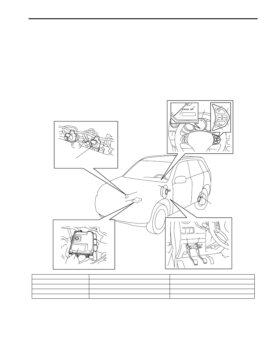
Cruise Control System Construction

S5JB0BA101001

The cruise control system is a device which maintains a preset vehicle speed while driving at a high speed, e.g., on a 
highway. It allows the driver to drive his vehicle at a constant speed of 40 km/h (25 mile/h) or higher without 
depressing the accelerator pedal. The system also has such functions as to change the vehicle speed without 
operating the accelerator pedal (but using SET/COAST and RES/ACC switches), cancel cruise control (CANCEL 
switch) and resume the speed in memory automatically after cruise control is cancelled (RES/ACC switch). The 
system mainly consists of fuel injectors, ECM, cruise control switch (MAIN switch, SET/COAST switch, RES/ACC 
switch and CANCEL switch), etc.

10

10

9

11

12

13

3

5

8

6

7

4

1

2

9

13

I5JB0BA10001-01

1. Combination meter

6. MAIN switch

11. Brake light switch with brake pedal position switch

2. “CRUISE” indicator lamp

7. SET/COAST switch

12. Clutch pedal position switch (M/T vehicle only)

3. “SET” indicator lamp

8. CANCEL switch

13. ECM

4. Cruise control switch assembly

9. Wheel speed sensor (vehicle speed signal)

5. RES/ACC switch

10. Fuel injectors

10A-2 Cruise Control System: 

Components and Functions of Cruise Control System

S5JB0BA101002

Component

Function

ECM and fuel injectors

ECM executes centralized control over all functions including setting a constant speed, 
resuming it, setting coast, cancelling cruise control limiting minimum speed.
ECM controls fuel injector to keep actual vehicle speed at set (target) speed.

MAIN switch

This switch has a momentary contact type button to press cruise control 
system ON and OFF.

SET/COAST switch

When this switch is pressed (ON) and then released (OFF) while vehicle is running at 
a speed 40 km/h (25 mile/h) or higher, vehicle speed at that OFF moment is stored in 
memory and it is maintained (constant cruising).
Pressing this switch (ON) continuously during constant cruising keeps slowing down 
vehicle speed as long as it is ON. When it is released (OFF), vehicle speed at that 
moment is stored in memory and vehicle starts constant cruising.

RES/ACC switch

When this switch is pressed (ON) during constant cruising, vehicle speed keeps 
increasing as long as it is ON. When it is released (OFF), vehicle speed at that 
moment is stored in memory and vehicle starts constant cruising. If vehicle speed is 
higher than 40 km/h (25 mile/h) after cruise control is cancelled, pressing this switch 
ON momentarily will resume the speed at which vehicle was running before 
cancellation.

CANCEL switch

When this switch is pressed (ON), cruise control is cancelled.

Wheel speed vehicle (sensor 
speed signal)

ECM receives speed sensor signal from ABS or ESP

® control module through CAN 

communication and calculates vehicle speed using that signal.

Brake light switch

Brake light switch has 2 contact points. One contact point closes when brake pedal is 
depressed to light brake light and provides a voltage signal to the ECM.
The other contact point (brake pedal position switch) opens when brake pedal is 
depressed, to shut off power to cruise control of ECM, thereby cancelling cruise 
control.
This switch is installed to cancel cruise control (constant cruising).

Clutch pedal position switch

When clutch pedal is depressed, clutch pedal position switch closes and provides a 
ground signal to ECM.
ECM cancels cruise control when this signal is inputted.

“CRUISE” indicator lamp

In the state with ignition switch ON and cruise control system OFF, pressing MAIN 
switch once and releasing it will activate the cruise control system and ECM will cause 
indicator lamp to light up.

“SET” indicator lamp

It lights up when cruise control is functioning.

Cruise Control System:  10A-3

Cancel Conditions of Cruise Control System

S5JB0BA101003

Constant cruising is cancelled under the following conditions.
• *Ignition switch is turned OFF.
• MAIN switch is turned OFF.
• Vehicle speed becomes lower than minimum operating speed (40 km/h (25 mile/h)).
• *Vehicle speed varies beyond cancel speed range (–10 km/h (–6 mile/h)) from preset speed.
• *Brake pedal is depressed. (Brake light switch is turned ON).
• *Clutch pedal is depressed (Clutch pedal position switch is turned ON) (For M/T vehicle).
• *CANCEL switch is turned ON.
• *ESP

® is operating (if equipped).

NOTE
When constant cruising is cancelled under any condition with * (asterisk), vehicle speed before 
cancellation can be resumed by operating RES/ACC switch, provided that vehicle speed is higher than 
40 km/h (25 mile/h).


Schematic and Routing Diagram

Cruise Control System Input / Output Diagram

S5JB0BA102002

Input

Output

MAIN switch

Cruise control switch

RES/ACC switch
SET/COAST switch

CANCEL switch

CPP switch

Stop (brake) lamp switch

Wheel speed sensor

ABS or ESP
control module 

ECM

Fuel injector

Combination meter
(Indicator lamp control)

I5JB0BA10002-01

10A-4 Cruise Control System: 

Cruise Control System Wiring Diagram

S5JB0BA102001

IG1

+BB

WHT

RED

WHT/BLU

WHT/RED E66-32

E66-26

E66-4

WHT

RED

E91-22
E91-23

WHT

RED

G28-10

G28-8

WHT

ORN

G31-3

G31-1

E66-17

E66-23

C86-3

C86-14

E66-11

E66-2

E66-3

E66-5

E66-15

E66-21

E66-27

WHT/BLU

BLK/WHT

LT GRN

BLK/YEL

BLU/BLK

BLU/BLK

BLK/WHT

BLU/YEL

BLU/BLK

BLU/GRN

BLU/YEL

ORN/BLU

16

18

2

17

14

15

1

3

4

5
6

7

12

13

[A]

E66-20

E66-8

E66-7

E66-1

BLK

BLK

BLK

E03-12
E03-6

E03-8

E03-10

E53-13
E53-44

WHT/BLU

WHT/RED

E53-46

E53-42

WHT

RED

[B]

[C]

33

34

39

40

41

42

43

44

35

36

37

38

45

46

47

48

9

10

11

12

13

14

1

3

5

7

2

4

6

8

15

16

17

18

19

20

21

22

23

24

25

26

27

28

29

30

31

32

1

3

7

15

16

17

18

19

20

21

22

23

24

25

26

27

28

29

30

31

32

2

4

6

8

9

10

11

12

13

14

5

1

2

3

4

5

6

7

8

9

10

11

12

13

14

15

16

17

18

19

20

21

22

23

24

25

26

27

28

29

30

31

32

C85

C86

E66

BLU

BLK

9

E66-30

IG1

E66-28

YEL/GRN

BLU/BLK

GRN/WHT

GRN

8

10

C85-8

11

11

11

11

C85-32

PNK

C85-27

RED

C85-29

PNK/BLK

C85-25

RED/BLK

C85-30

PNK/GRN

C85-26

RED/GRN

C85-31

PNK/BLU

C85-28

RED/BLU

I5JB0BA10003-01

[A]: ECM connector (viewed from harness side)

5. RES/ACC switch

12. Main relay

[B]: Vehicle equipped with ESP

®

6. SET/COAST switch

13. Ignition switch

[C]: Vehicle not equipped with ESP

®

7. CANCEL switch

14. ABS control module

1. ECM

8. Stop (brake) lamp switch

15. ESP

® control module

2. Accelerator pedal position sensor

9. CPP switch

16. Combination meter

3. Cruise control switch assembly

10. Brake lamp

17. BCM

4. MAIN switch

11. Fuel injector

18. 4WD control module (if equipped)


Content   ..  171  172  173  174   ..