Suzuki Grand Vitara JB627. Manual - part 374
9B-21 Lighting Systems:
A
A
4
3
B
B
[A]
[B]
A
A
4
B
B
[A]
[B]
11
2
1
7
6
5
12
12
5
10
9
8
10
9
8
7
6
“b”
“a”
“H”
“H”
“H”
“H”
“H”
[F]
[E]
[C]
[D]
A
A
4
B
B
[A]
[B]
“H”
“H”
X
X
X
X
X
X
A
A
4
B
B
[A]
[B]
“H”
“H”
[F]
[E]
[F]
[E]
3
3
3
3
3
3
3
X
X
I5JB0A920022-04
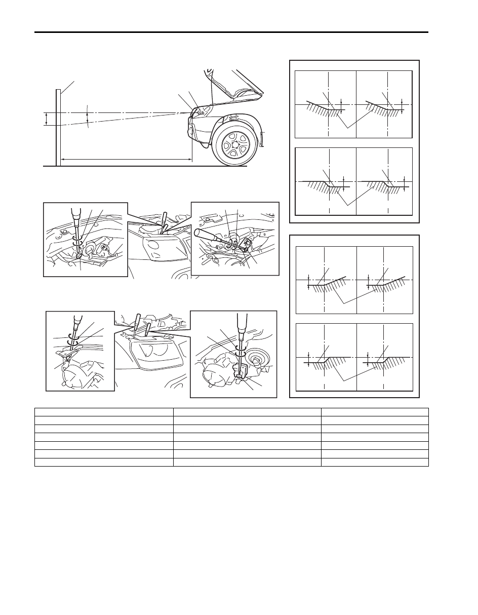
2. Headlight bulb
9. Turning (for right adjustment)
[A]: Left headlight
3. Cut line (bounding line)
10. Turning (for left adjustment)
[B]: Right headlight
4. Hot spot
11. Headlight housing
[C]: RH steering vehicle shown
5. Aiming gear (for up / down adjustment)
12. Headlight leveling actuator
[D]: LH steering vehicle shown
6. Turning (for up adjustment)
X-X: Horizontal center line of headlight bulbs
[E]: 3 door model
7. Turning (for down adjustment)
A-A: Vertical center line of left headlight bulb
[F]: 5 door model
8. Aiming gear (for right / left adjustment)
B-B: Vertical center line of right headlight bulb