Suzuki Grand Vitara JB627. Manual - part 272
7B-4 Air Conditioning System:
General Description
AUTO A/C System Description
S6JB0B7201001
The automatic air conditioning system (auto A/C), HVAC
control module automatically controls inside air
temperature, blower speed, airflow outlet and so forth.
Once users set up desired inside air temperature with
the temperature control selector, select “AUTO” position
of blower speed selector, push “AUTO” switch of mode
selector and push A/C switch, HVAC control module
detects inside air temperature, outside air temperature,
amount of sunlight, and engine coolant temperature by
means of inside air temperature sensor, outside air
temperature sensor, sunload sensor, and engine coolant
temperature (ECT) sensor respectively.
Then, HVAC control module keeps desired in-car
temperature at any time.
Then, HVAC control module keeps in-car temperature at
desired level.
HVAC Control System Description
S6JB0B7201002
For CAN communication system, refer to description on
“CAN Communication System Description in Section
1A”.
When following data are sent from control modules to
BCM through CAN communication, they are sent from
BCM to HVAC control module through serial
communication line.
• Engine coolant temperature
• Engine speed
• A/C refrigerant pressure
• Vehicle Speed (wheel speed)
• Outside air temperature
Based on above data, HVAC control module sends A/C
compressor ON / OFF request signal to BCM through
serial communication line.
BCM sends this signal through CAN communication to
ECM which then causes compressor relay to turn ON /
OFF.
For more information on signal transmission and
reception of Auto A/C system, refer to “Auto A/C
Electronic Control Input / Output Diagram”.
HVAC control module has a function to make initial
settings of temperature control actuator, air intake
actuator and air flow actuator.
Initial settings of actuators are automatically made when
engine is started for the first time after battery is
connected.
When initial settings are made, each actuator is forced to
operate for about 15 seconds continuously.
HVAC Control Module Operation Description
S6JB0B7201004
Temperature Control
HVAC control module calculates the target temperature
control door position based on signals from the
temperature selector, inside air temperature sensor,
outside air temperature sensor and sunload sensor and
controls the temperature control actuator so that the
current position of the temperature control door matches
its target position.
Fan Speed Control
HVAC control module calculates the target blower fan
speed based on signals from the temperature selector,
inside air temperature sensor, outside air temperature
sensor and sunload sensor, compares it with the current
blower fan speed inputted from the blower motor
controller to control the current blower fan speed to the
target level.
Air Flow Outlet Control
HVAC control module calculates the target temperature
control door position based on signals from the
temperature selector, inside air temperature sensor,
outside air temperature sensor and sunload sensor.
Using thus obtained target temperature control door
position, it further calculates the target air flow control
door position and controls the air flow control actuator so
that the current air flow control door position becomes
the target position.
Air Intake Position Control
HVAC control module determines the air intake position
based on signals from the temperature selector, inside
air temperature sensor, outside air temperature sensor
and sunload sensor and controls the air intake actuator.
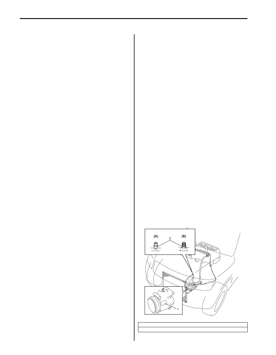
A/C Refrigerant Type Description
S6JB0B7201005
Whether the A/C in the vehicle being serviced uses
HFC-134a (R-134a) or CFC-12 (R-12) is indicated on
LABEL (1) on the compressor. Also, it can be checked
by the shape of the service (charge) valve (2).
[A]: HFC-134a (R-134a)
[B]: CFC-12 (R-12)
I5JB0A720005-01