Suzuki Grand Vitara JB627. Manual - part 225


  Index      Suzuki     Suzuki Grand Vitara JB627 - service repair manual


Search            


Content   ..  223  224  225  226   ..


Suzuki Grand Vitara JB627. Manual - part 225


5A-84 Automatic Transmission/Transaxle: 

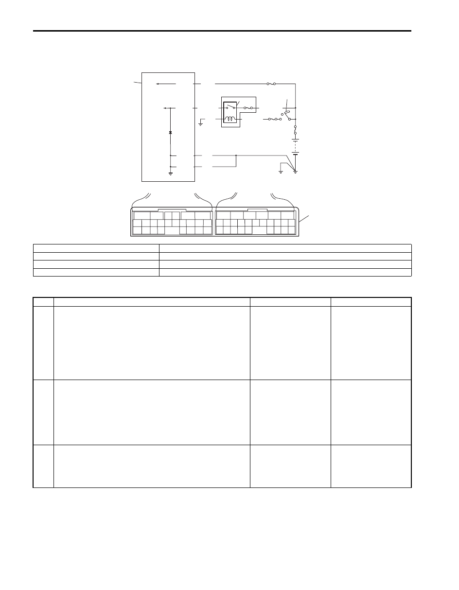
TCM Power and Ground Circuit Check

S6JB0B5104050

Wiring Diagram

Troubleshooting

BLK

BLK

BLK

E92-1

E92-23

E92-6

BLK/WHT

BLK/WHT

WHT/GRN

E92-24

WHT

1

2

3

4

7

6

5

6

5

16 15 14 13 12 11

4 3

24 23

21

22

10 9

8

7

2

1

19

20

18 17

E92

17 16

26 25

15 14

6

5

3

4

2

13 12

23 22

24

11 10 9

21 20 19

8 7

18

1

E93

8

I5JB0A510152-01

1. TCM

5. Ignition switch

2. A/T relay

6. “IG COIL” fuse

3. “AT” fuse

7. Power integration No.2 in main fuse box

4. “DOME” fuse

8. Terminal arrangement of TCM connector (viewed from harness side)

Step

Action

Yes

No

1

Check TCM back-up power circuit
1) Disconnect TCM connector with ignition switch OFF.
2) Check for proper connection to TCM at “E92-24” 

terminal.

3) If OK, check voltage at terminal “E92-24” of 

disconnected TCM connector.

Is it 10 – 14 V?

Go to Step 2.

“WHT” circuit open or 
shorted to ground.

2

Check TCM power circuit
1) Disconnect TCM connector with ignition switch OFF.
2) Check for proper connection to TCM at “E92-6” terminal.
3) If OK, turn ignition switch ON and check voltage at 

terminal “E92-6” of disconnected TCM connector.

Is it 10 – 14 V?

Go to Step 4.

Go to Step 3.

3

Check A/T relay operation
1) Check A/T relay operation referring to “A/T Relay 

Inspection”.

Is check result satisfactory?

“BLK/WHT”, “WHT/
GRN”, or “BLK” circuit 
for power supply open.

Replace A/T relay 
included in power 
integration No.2 in main 
fuse box.

Automatic Transmission/Transaxle:  5A-85

Repair Instructions

Learning Control Initialization

S6JB0B5106001

1) Connect scan tool to DLC (1) with ignition switch 

OFF.

Special tool
(A):  SUZUKI scan tool 

2) Start engine and shift selector lever to “P” range.
3) Select “Misc Test” mode on scan tool.
4) Perform “AT learned initialize” on scan tool.

A/T Fluid Level Check

S6JB0B5106002

At Normal Operating Temperature

1) Drive vehicle so that A/T fluid temperature reach the 

normal operating temperature (70 – 80 

°C (158 – 

176 

°F)).

2) Stop vehicle with engine running and place it level.
3) With select lever at “P” range, apply parking brake 

and place chocks against wheels.

4) Keep engine idling and shaft selector slowly to “L” 

and back to “P” range.

5) With engine idling, pull out dipstick (1), wipe it off 

with a clean cloth and put it back into place.

6) Pull out dipstick (1) again and check fluid level 

indicated on it. Fluid level should be between FULL 
HOT and LOW HOT. If it is below LOW HOT, add 
specified A/T fluid up to FULL HOT.

A/T fluid specification
SUZUKI ATF 3317 or Mobil ATF 3309

NOTE

• DO NOT RACE ENGINE while checking 

fluid level, even after engine is started.

• DO NOT OVERFILL. Overfilling can causes 

foaming and loss of fluid through breather. 
Then slippage and transmission failure can 
result.

• If vehicle was driven under high load such 

as pulling a trailer, fluid level should be 
checked about half an hour after it is 
stopped.


4

Replace A/T relay included in power integration No.2 in 
main fuse box.
1) Turn ignition switch OFF.
2) With TCM connectors disconnected, check for proper 

connection to TCM at “E92-1” / “E92-23” terminal.

3) If OK, check resistance between “E92-1” / “E92-23” 

terminal of disconnected TCM connector and body 
ground.

Is continuity indicated?

TCM power and ground 
circuits are in good 
condition.

“BLK” circuit for TCM 
ground open.

Step

Action

Yes

No

(A)

1

I6JB01510049-01

2. “FULL HOT”

4. “FULL COLD”

3. “LOW HOT”

5. “LOW COLD”

1

H

C

2

3

4

5

I6JB01510025-01

5A-86 Automatic Transmission/Transaxle: 

At Room Temperature
The fluid level check at room temperature performed 
after repair or fluid change before test driving is just 
preparation for level check of normal operating 
temperature. The checking procedure itself is the same 
as that described in “At Normal Operating Temperature: 
”. 
If the fluid level is between FULL COLD and LOW 
COLD, proceed to test drive. And when the fluid 
temperature has reached the normal operating 
temperature, check fluid level again and adjust it as 
necessary.

A/T Fluid Change

S6JB0B5106003

1) Lift up vehicle.
2) When engine is cool, remove drain plug (1) from oil 

pan and drain A/T fluid.

3) Install drain plug with new gasket.

Tightening torque
A/T fluid drain plug (a):  20 N·m (2.0 kgf-m, 14.5 
lb-ft)

4) Lower vehicle and fill proper amount of specified 

fluid.

5) Check fluid level referring to “At Normal Operating 

Temperature” under “A/T Fluid Level Check”.

A/T fluid specification
: SUZUKI ATF 3317 or Mobil ATF 3309

A/T fluid capacity reference value
When draining from drain plug hole: Approx. 3.0 
liters (6.34/5.28 US/lmp. pt.)
When overhauling: Approx. 9.9 liters (20.92/17.42 
US/lmp. pt.)

1. Dipstick

3. “LOW COLD”

2. “FULL COLD”

1

H

C

2

3

I6JB01510017-02

1. Dipstick

4. “FULL COLD”

2. “FULL HOT”

5. “LOW COLD”

3. “LOW HOT”

1, (a)

I5JB0A510030-03

1

H

C

2

3

4

5

I6JB01510025-01

Automatic Transmission/Transaxle:  5A-87

Oil Cooler Hoses Replacement

S6JB0B5106004

When replace them, make sure to note the followings.
• to replace clamps at the same time
• to insert hose as far as bulge of pipe
• to clamp hose securely

[A]

1

6

5

A

6

4

8

5

7

1

2

3

9

10

(b)

(c)

(a)

I6JB01510018-01

[A]: View from A side

3. Oil hose No.2

6. Oil hose No.4

9. Oil pipe No.1 bolt

: 23 N

⋅m (2.3 kgf-m, 17.0 lb-ft.)

1. Radiator

4. Oil hose No.3

7. Oil pipe No.1

10. Oil pipe No.2 bolt

: 10 N

⋅m (1.0 kgf-m, 7.5 lb-ft.)

2. Oil pipe union bolt

5. Oil hose No.1

8. Oil pipe No.2

: 25 N

⋅m (2.5 kgf-m, 18.0 lb-ft.)


Content   ..  223  224  225  226   ..