Suzuki Grand Vitara JB627. Manual - part 172


  Index      Suzuki     Suzuki Grand Vitara JB627 - service repair manual


Search            


Content   ..  170  171  172  173   ..


Suzuki Grand Vitara JB627. Manual - part 172


4A-7 Brake Control System and Diagnosis: 

Repair Instructions

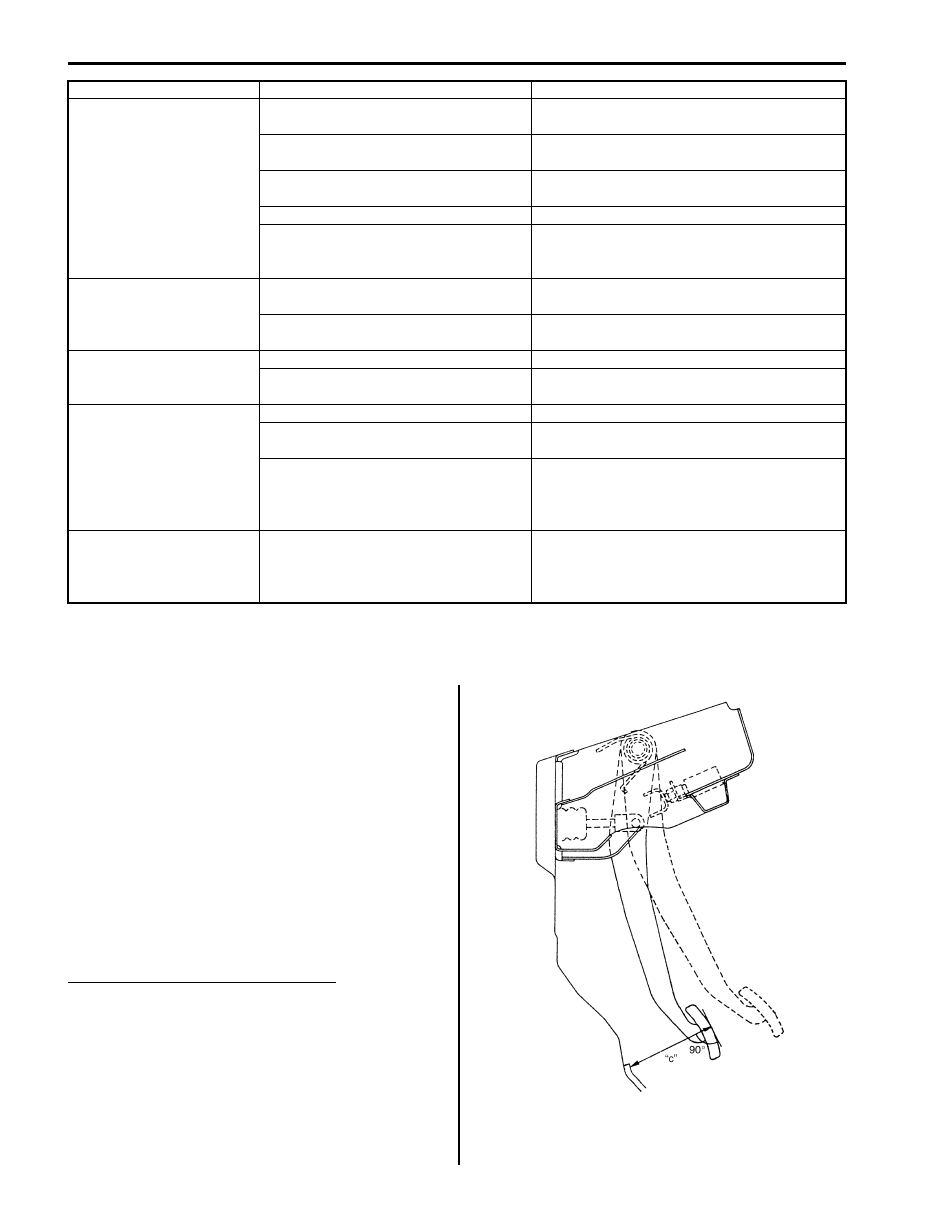
Excessive Pedal Travel Check

S6JB0B4106001

1) Start engine.
2) Depress brake pedal a few times.
3) With brake pedal depressed with approximately 30 

kg (66 lbs) load, measure pedal to carpet clearance 
“c”.
If clearance “c” is less than specification, the most 
possible cause is either rear brake shoes are worn 
out beyond limit or air is in lines.
Should clearance “c” remain less than specification 
even after replacement of brake shoes and bleeding 
of system, other possible but infrequent cause is 
malfunction of rear brake shoe adjusters or booster 
push rod length out of adjustment.

Brake pedal arm to wall clearance “c”
When pedal depressed at 300 N (30 kg, 66 lbs): Over 
70 mm (2.75 in.)

Brake warning light turns 
ON after engine start

Parking brake applied

Release parking brake and check that brake 
warning light turns off.

Insufficient amount of brake fluid

Investigate leaky point, correct it and add 
brake fluid.

Brake fluid leaking from brake line

Investigate leaky point, correct it and add 
brake fluid.

Brake warning light circuit faulty

Repair circuit.

Malfunctioning EBD system

Check system referring to “ABS Check in 
Section 4E”
 or “ESP

®

 Warning Light Comes 

ON Steady in Section 4F”.

Brake warning light turns 
on when brake is applied

Brake fluid leaking from brake line

Investigate leaky point, correct it and add 
brake fluid.

Insufficient amount of brake fluid

Investigate leaky point, correct it and add 
brake fluid.

Brake warning light fails 
to turn on even when 
parking brake is applied

Bulb burnt out

Replace bulb.

Brake warning light circuit faulty

Repair circuit.

ABS warning light does 
not turn ON for 2 – 3 sec. 
after ignition switch has 
turned ON

Bulb burnt out

Replace bulb.

ABS warning light circuit open (including 
check relay)

Repair or replace.

Malfunctioning ABS (ESP

®)

Check system referring to “ABS Warning Light 
Does Not Come ON at Ignition Switch ON in 
Section 4E” or
 “ESP

®

 Warning Light Does Not 

Come ON at Ignition Switch ON in Section 4F”.

ABS warning light 
remains ON after ignition 
switch has turned ON for 
2 – 3 sec.

Malfunctioning ABS (ESP

®)

Check system referring to “ABS Warning Light 
Comes ON Steady in Section 4E” or
 “ESP

®


Warning Light Comes ON Steady in Section 
4F”.

Condition

Possible cause

Correction / Reference Item

IYSQ01410009-01

Brake Control System and Diagnosis:  4A-8

Brake Pedal Play Check

S6JB0B4106002

Pedal play should be within specification. If out of 
specification, check brake light switch for proper 
installation position and adjust if necessary.
Also check pedal shaft bolt and master cylinder pin 
installation for looseness and replace if defective.

Brake pedal play “d”
: 1 – 8 mm (0.04 – 0.32 in.)

Brake Fluid Level Check

S6JB0B4106003

Be sure to use particular brake fluid either as indicated 
on reservoir cap of that vehicle or recommended in 
owner’s manual which comes along with that vehicle. 
Use of any other fluid is strictly prohibited.
Fluid level should be between MIN and MAX lines 
marked on reservoir.
When warning light lights sometimes during driving, 
replenish fluid to MAX line.
When fluid decreases quickly, inspect brake system for 
leakage. Correct leaky points and then refill to specified 
level.

CAUTION

!


Do not use shock absorber fluid or any other 
fluid which contains mineral oil. Do not use a 
container which has been used for mineral oil 
or a container which is wet from water. 
Mineral oil will cause swelling and distortion 
of rubber parts in hydraulic brake system and 
water mixed into brake fluid will lower fluid 
boiling point. Keep all fluid containers 
capped to prevent contamination.


Air Bleeding of Brake System

S6JB0B4106004

CAUTION

!


Brake fluid is extremely damaging to paint. If 
fluid should accidentally touch painted 
surface, immediately wipe fluid from paint 
and clean painted surface.


Bleeding operation is necessary to remove air whenever 
it entered hydraulic rake system.
Hydraulic lines of brake system are based on the 
diagonal split system. When a brake pipe or hose was 
disconnected at the wheel, bleeding operation must be 
performed at both ends of the line of the removed pipe or 
hose. When any joint part of the master cylinder of other 
joint part between the master cylinder and each brake 
(wheel) was removed, the hydraulic brake system must 
be bled at all 4 wheel brakes.

NOTE
Perform bleeding operation starting with 
wheel cylinder farthest from master cylinder 
and then at front caliper of the same brake 
line. Do the same on the other brake line.


1) Fill master cylinder reservoir with specified brake 

fluid and keep at least one-half full of fluid during 
bleeding operation.

2) Remove bleeder plug cap.

Attach a vinyl tube (1) to bleeder plug of wheel 
cylinder, and insert the other end into container (2).

IYSQ01410010-01

I5JB0A410005-01

1. Right brake caliper

4. Left wheel cylinder

2. Left brake caliper

[A]: FRONT

3. Right wheel cylinder

[B]: REAR

I2RH01410013-01

I2RH01410015-01

4A-9 Brake Control System and Diagnosis: 

3) Depress brake pedal several times, and then while 

holding it depressed, loosen bleeder plug about one-
third to one half turn.

4) When fluid pressure in the cylinder is almost 

depleted, retighten bleeder plug.

5) Repeat this operation until there are no more air 

bubbles in hydraulic line.

6) When bubbles stop, depress and hold brake pedal 

and tighten bleeder plug.

Tightening torque
Front brake caliper bleeder plug:  7 N·m (0.7 kgf-
m, 5.0 lb-ft)
Rear wheel cylinder bleeder plug:  7 N·m (0.7 
kgf-m, 5.0 lb-ft)

7) Then attach bleeder plug cap.
8) After completing bleeding operation, apply fluid 

pressure to pipe line and check for leakage.

9) Replenish fluid into reservoir up to “MAX” level.

10) Check brake pedal for “sponginess”. If found spongy, 

repeat entire procedure of bleeding.

Brake Pedal Free Height Adjustment

S6JB0B4106005

Measure brake pedal free height between pedal and 
carpet installed on dash panel.
If the measurement is not within the specification, check 
the position of booster push rod clevis and/or brake light 
switch, referring to, “Master Cylinder Assembly 
Inspection”,
 “Booster Push Rod Clevis Adjustment” and/
or “Brake Light Switch Adjustment”. The free height 
varies depending on installation position of booster push 
rod clevis and brake light switch.

Brake pedal free height “a” from carpet
“a”: 131 – 141 mm (5.16 – 5.55 in.)

1. MAX level mark

I2RH01410016-01

I2RH01410017-01

1

I5JB0A410006-01

IYSQ01410007-01

Brake Control System and Diagnosis:  4A-10

Brake Light Switch Adjustment

S6JB0B4106006

CAUTION

!


Do not apply any oil or grease (including rust 
preventives, lubricant, etc.) to following 
sections.
* Brake light switch (1) (including its tip end)
* Switch (1) contacting section of brake pedal 
stay (3)
Oil or grease, if applied, will enter the contact 
point in the switch, causing contact failure. 
Also, when checking, adjusting or replacing 
brake switch, check that no oil or grease is 
attached to switch contacting section on 
brake pedal side or tip end of switch.
Wipe off oil or grease being attached.


Adjustment should be made as follows when installing 
switch (1). Pull up brake pedal toward you and while 
holding it there, adjust switch position so that clearance 
between end of switch thread (2) and brake pedal stay 
(3).

Clearance “b” between end of thread and brake 
pedal stay 
“b”: 1.5 – 2.5 mm (0.06 – 0.10 in.)

Brake Flexible Hose and Pipe Check

S6JB0B4106007

The brake hose assembly should be checked for road 
hazard damage, for cracks and chafing of the flexible 
hose, for leaks and blisters. A light and mirror may be 
needed for an adequate inspection. If any of the above 
conditions are observed on the brake flexible hose, it is 
necessary to replace it.
Inspect the pipe for damage, cracks, dents and 
corrosion. If any defect is found, replace it.

Master Cylinder Check

S6JB0B4106008

Check for a cracked master cylinder casting or brake 
fluid around the master cylinder. Leaks are indicated 
only if there is at least a drop of fluid. A damp condition is 
not abnormal.

Flushing Brake Hydraulic System

S6JB0B4106009

It is recommended that entire hydraulic system be 
thoroughly flushed with clean brake fluid whenever new 
parts are installed in hydraulic system.
Periodical change of brake fluid is also recommended.

3

2

1

I3JA01410004-01

I5JB0A410007-01

I5JB0A410005-01


Content   ..  170  171  172  173   ..