Suzuki Grand Vitara JB627. Manual - part 163


  Index      Suzuki     Suzuki Grand Vitara JB627 - service repair manual


Search            


Content   ..  161  162  163  164   ..


Suzuki Grand Vitara JB627. Manual - part 163


3C-56 Transfer: 

Transfer Assembly Dismounting and 
Remounting

S6JB0B3306007

Dismounting

1) Shift transfer to 4H position operating transfer 

switch.

2) Disconnect negative (–) cable from battery.
3) Remove gear shift control lever (for M/T model) 

referring to “Transmission Shift Control Lever 
Removal and Installation in Section 5B”.

4) Drain transfer oil.
5) Remove front propeller shaft (1) and rear propeller 

shaft (2) referring to “Propeller Shaft Removal and 
Installation in Section 3D”.

6) Remove exhaust center pipe (3) referring to “Muffler 

Removal and Installation in Section 1K”.

7) Disconnect transfer actuator connector (4), center 

differential lock switch connector (5), 4L/N switch 
connector (6).

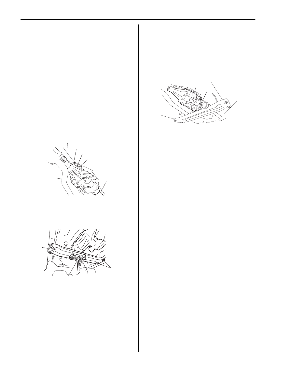
8) Support engine rear mounting member (1) with 

transmission jack (2).

9) Remove engine rear mounting bolts (3), and then 

slant the transmission with transfer.

10) Remove gear shift control lever rear case from 

transfer (for M/T model).

11) Remove transfer to transmission bolts (upper side), 

and then install engine rear mounting member with 
transmission and transfer.

12) Support transfer assembly (1) with transmission 

jack.

13) Remove transfer to transmission bolts (lower side) 

(2), and then lower transfer assembly.

Remounting
Reverse dismounting procedure for remounting noting 
the following.
• Tighten each bolts and nuts referring to “Transfer 

Assembly Components”, “Propeller Shaft 
Construction in Section 3D”
, “Exhaust System 
Components in Section 1K”,
 “Gear Shift Control Lever 
Rear Case Assembly Components in Section 5B” an

“Transmission Shift Control Lever Removal and 
Installation in Section 5B”.

• Set each clamp for wiring securely.
• Fill transfer oil referring to “Transfer Oil Change”.
• Connect battery and check for function.

1

4

3

6

5

2

I5JB0A331006-01

1

2

3

I5JB0A331007-02

1

2

I5JB0A331008-01

Transfer: 3C-57

Transfer Assembly Components

S6JB0B3306008

11

16

44

45

42

43

41

40

9

(c)

(a)

39

38

(b)

37

(a)

37

35

(a)

(a)

1217G

10

1217G

33

32

30

31

1217G

34

1217G

48

A

OIL

9

28

27

OIL

9

OIL

OIL

9

OIL

9

OIL

19

29

19

47

A

26

25

24

23

22

4

5

7

6

21

20

OIL

9

OIL

2

(a)

2

3

8

(a)

46

(a)

1

A

9

OIL

12

(d)

13

17

(d)

15

(a)

1322

49

50

18

OIL

18

14

(b)

I5JB0A331009-06

3C-58 Transfer: 

Transfer Assembly Disassembly and 
Reassembly

S6JB0B3306009

Disassembly

1) Remove harness bracket (1).

2) Remove center differential lock switch (1) and 4L/N 

switch (2).

3) Remove transfer actuator assembly (3) and breather 

pipe (4).

4) Remove oil pump cover (1).

5) Remove oil pump inner rotor (1), outer rotor (2), oil 

strainer (4) and drive pin (3).

 1. Front oil seal No.1

: Apply grease 99000-25010 to oil seal lip.

20. Washer

39. Oil strainer bolt

2. Front case bolt

21. Shim

40. Oil pump outer rotor

3. Front case

22. Reduction shift sleeve

41. Oil pump inner rotor

4. Knock pin

23. Center differential assembly

42. Oil pump drive pin

5. Oil pipe

24. Low gear

43. Oil strainer bolt

6. Input gear assembly

25. Front drive shaft

44. Oil pump cover bolt

7. Input gear plate bolt

26. Thrust needle bearing

 45. Oil drain plug

: Apply sealant 99000-31260 to 
plug thread.

8. Counter gear assembly

27. Differential lock clutch sleeve

46. Transfer to transmission bolt

9. Needle bearing

28. Front drive sprocket bush

 47. Front oil seal No.2

: Apply grease 99000-25010 to oil 
seal lip.

 10. Center case

: Apply sealant 99000-31260 to mating 
surface of front case, transfer control 
cover and center case.

29. Front drive sprocket

 48. Rear oil seal

: Apply grease 99000-25010 to oil 
seal lip.

11. Damper

30. Rear output shaft assembly

49. Transfer actuator bolt

12. 4L/N switch

31. Front output shaft assembly

50. Control cover

13. Center differential lock switch

32. Drive chain

: 23 N

⋅m (2.3 kgf-m, 17.0 lb-ft)

14. Transfer actuator assembly

 33. Rear case

: Apply sealant 99000-31260 to mating 
surface of rear case, oil pump cover and 
center case.

: 10  N

⋅m (1.0 kgf-m, 7.5 lb-ft)

 15. Control cover bolt

: Apply thread lock 99000-32110 to bolt 
thread.

 34. Oil level / filler plug

: Apply sealant 99000-31260 to plug 
thread.

: 50  N

⋅m (5.0 kgf-m, 36.5 lb-ft)

16. Damper bolt

35. Harness bracket

: 20 N

⋅m (2.0 kgf-m, 14.5 lb-ft)

17. Breather pipe

36. Harness bracket bolt

: Do not reuse.

18. O-ring

37. Rear case bolt

: Apply transfer oil.

19. Snap ring

38. Oil strainer

1

1

I5JB0A331010-01

2

1

3

4

I5JB0A331011-01

1

I5JB0A331012-01

1

2

4

3

I5JB0A331013-01

Transfer: 3C-59

6) Remove front case (1) using plastic hammer.

7) Remove rear case bolts (1) and clamp (2) and then 

separate center case (3) using special tool.

Special tool
(A):  09912–34510

8) Remove knock pin (1) and oil pipe (2) from center 

case (4) and remove front oil seal No.1 (3) using flat 
end rod or the like, if necessary.

9) Remove needle bearings (1) from center case (2) 

using special tools, if necessary.

Special tool
(A):  09913–76010
(B):  09925–98210

10) Remove needle bearing (1), snap ring (2), washer 

(3) and shim(s) (4) from rear output shaft (5).

11) Remove reduction shift sleeve (1), center differential 

and low gear from rear output shaft (2).

1

I5JB0A331014-01

1

2

I5JB0A331015-01

3

(A)

I5JB0A331106-01

1

2

3

4

I5JB0A331017-01

(A)

(B)

1

2

I5JB0A331018-01

1

2

3

4

5

I5JB0A331019-01

1

2

I5JB0A331020-02


Content   ..  161  162  163  164   ..