Suzuki Grand Vitara JB627. Manual - part 105


  Index      Suzuki     Suzuki Grand Vitara JB627 - service repair manual


Search            


Content   ..  103  104  105  106   ..


Suzuki Grand Vitara JB627. Manual - part 105


1G-3 Fuel System: 

Diagnostic Information and Procedures

Fuel Pressure Inspection

S6JB0B1704001

WARNING

!


Before starting the following procedure, be 
sure to observe “Precautions on Fuel System 
Service” 
in order to reduce the risk or fire 
and personal injury.


1) Relieve fuel pressure in fuel feed line referring to 

“Fuel Pressure Relief Procedure”.

2) Disconnect fuel feed hose from fuel No.2 pipe.
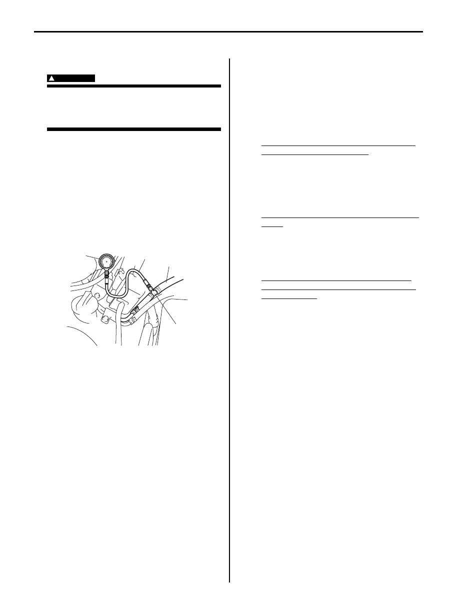
3) Connect special tools and hose between fuel feed 

hose (1) and fuel No.2 pipe as shown in figure, and 
clamp hoses securely in order to ensure that no 
leaks occur during checking.

Special tool
(A):  09912–58442
(B):  09912–58432
(C):  09912–58490

4) Check that battery voltage is 11 V or more.
5) Measure fuel pressure at each condition.

If measured pressure is out of specification, refer to 
“Fuel Pressure Check in Section 1A” and check each 
possibly defective part. Replace if found defective.
a) Turn ignition switch ON to operate fuel pump and 

after 2 seconds turn it OFF. Repeat this 3 or 4 
times and then check fuel pressure.

Fuel pressure specification with fuel pump 
operating and engine stopped
: 250 – 310 kPa (2.5 – 3.1 kg/cm

2

, 35.5 – 44.0 

psi)

b) Start engine and warm it up to normal operating 

temperature, and measure fuel pressure at 
idling.

Fuel pressure specification at specified idle 
speed
: 210 – 260 kPa (2.1 – 2.6 kg/cm

2

, 29.9 – 36.9 

psi)

c) Stop engine, and measure fuel pressure at one 

minute after stopping.

Fuel pressure specification in 1 min. after 
engine (fuel pump) stop (Pressure reduces 
as time passes)
Over 180 kPa (1.8 kg/cm

2

, 25.6 psi)

(C)

1

(A)

(B)

I6JB01170002-01

Fuel System:  1G-4

6) After checking fuel pressure, remove fuel pressure 

gauge.

WARNING

!


As fuel feed line is still under high fuel 
pressure, make sure to release fuel pressure 
according to the following procedures.
• Place fuel container under joint.
• Cover joint with rag and loosen joint nut 

slowly in order to release fuel pressure 
gradually.


7) Remove special tools from fuel No.2 pipe and fuel 

feed hose.

8) Connect fuel feed hose to fuel No.2 pipe and clamp it 

securely.

9) With engine OFF and ignition switch ON, check for 

fuel leaks.

Fuel Cut Operation Inspection

S6JB0B1704002

NOTE
Before inspection, make sure that gear shift 
lever is in neutral position (shift select lever 
is “P” range for A/T vehicle), A/C is OFF and 
parking brake lever is pulled all the way up.


1) Warm engine up to normal operating temperature.
2) While listening to sound of injector (2) by using 

sound scope (1) or such, increase engine speed to 
higher than 3,000 r/min.

3) Check to make sure that injector operation sound is 

stop when throttle valve is closed instantly and it is 
heard again when engine speed is reduced to 
approx. 2,000 r/min or less.

I2RH01170032-01

I6JB01170003-01

1G-5 Fuel System: 

Repair Instructions

Fuel System Components

S6JB0B1706001

11

(b)

13

2

26

1

27

10

9

10

30

5

3

4

8-1

8-2

14

(a)

12

15

15

16

(c)

19

19

20

23

(b)

25

17

18

31

24

(d)

24

(d)

24

(d)

28

28

28

32

6

7

21

33

22

(e)

29

21

I6JB0B170003-01

1. Fuel tank

14. Fuel filler neck

28. Fuel delivery pipe gasket

2. Fuel pump assembly

15. Fuel delivery pipe

29. O-ring

3. Fuel recirculation hose

16. Fuel delivery pipe bolt

30. Fuel suction hose

4. Fuel tank filler hose

17. Fuel injector

31. Fuel connect pipe

5. Fuel filler cap

18. Injector cushion 

32. Fuel No.1 pipe

6. Fuel feed line

19. Fuel delivery pipe insulator

33. Fuel No.2 pipe

7. Fuel return line

20. Fuel pressure regulator

34. Fuel EVAP valve assembly (included in fuel tank)

: Securely insert hook through end of bracket.

8-1. Fuel tank inlet valve (fuel filler neck side)

21. To canister

: Do not reuse.

8-2. Fuel tank inlet valve (fuel tank side)

22. Fuel pipe clamp bolt

: 50 N

⋅m (5.0 kgf-m, 36.5 lb-ft)

9. Fuel tank protector

23. Fuel pressure regulator bolt

: 11 N

⋅m (1.1 kgf-m, 8.0 lb-ft)

Fuel System:  1G-6

Fuel Hose Disconnecting and Reconnecting

S6JB0B1706002

WARNING

!


Before starting the following procedure, be sure to observe “Precautions on Fuel System Service” in 
order to reduce the risk or fire and personal injury.


Be sure to connect and clamp each hose correctly as shown in figure.

For Normal Clamp
Fuel tank system

NOTE
Be sure to install hose to spool of pipe surely.


10. Fuel tank belt

24. Fuel union bolt

: 25 N

⋅m (2.5 kgf-m, 18.0 lb-ft)

11. Fuel pump gasket

25. To EVAP canister purge valve

: 30 N

⋅m (3.0 kgf-m, 22.0 lb-ft)

12. Fuel tank bolt

26. Sub fuel level sensor

: 5 N

⋅m (0.5 kgf-m, 3.6 lb-ft)

13. Fuel pump nut

27. Main fuel level sensor

I7JB01170002-01

1. Pipe

5. Vehicle forward

“d”: 25 – 30 mm (0.98 – 1.18 in.)

: 4 N

⋅m (0.4 kgf-m, 3.0 lb-ft)

2. Hose

“a”: 3 – 7 mm (0.12 – 0.28 in.)

“e”: 33 mm (1.30 in.)

3. Clamp

“b”: 5 – 12 mm (0.20 – 0.48 in.)

“f”: 38 mm (1.50 in.)

4. Fuel filler hose clamp screw

“c”: 2 mm (0.08 in.)

“g”: 8 – 15 mm (0.32 – 0.59 in.)


Content   ..  103  104  105  106   ..