Suzuki Grand Vitara JB627. Manual - part 84


  Index      Suzuki     Suzuki Grand Vitara JB627 - service repair manual


Search            


Content   ..  82  83  84  85   ..


Suzuki Grand Vitara JB627. Manual - part 84


1D-17 Engine Mechanical: 

Engine Assembly Removal and Installation

S6JB0B1406012

Removal

1) Release fuel pressure in fuel feed line referring to 

“Fuel Pressure Relief Procedure in Section 1G”.

2) Remove battery and battery tray.
3) Remove surge tank cover.
4) Remove air cleaner assembly and air cleaner outlet 

hose referring to “Air Intake System Components”.

5) Drain engine oil referring to “Engine Oil and Filter 

Change in Section 0B”.

6) Drain coolant referring to “Cooling System Draining 

in Section 1F”.

7) Drain transmission oil or A/T fluid referring to 

“Manual Transmission Oil Change in Section 5B” or 
“A/T Fluid Change in Section 5A”.

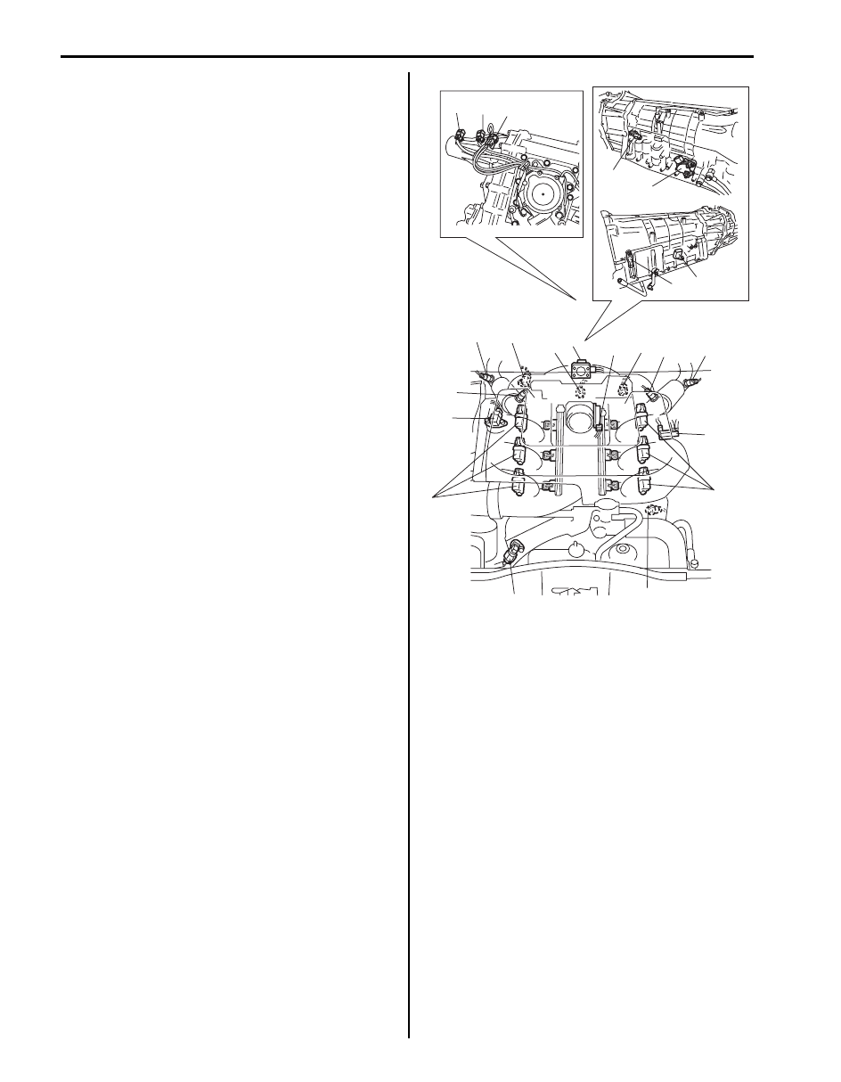
8) Disconnect the following electric wires.

• MAP sensor (if equipped) (1)
• Injector harness
• Electric throttle body (2)
• EVAP canister purge valve (3)
• Ignition coil assemblies (4)
• CMP sensor (5)
• Generator
• Starting motor
• Pressure switch of P/S pump (6)
• Magnet clutch switch of A/C compressor (if 

equipped)

• Engine oil pressure switch
• Ground terminals
• Knock sensor (7)
• CKP sensor (8)
• A/F sensor (No.1 and No.2) (9)
• HO2S (No.1 and No.2) (if equipped) (10)
• EGR valve (if equipped) (11)
• ECT sensor (12)
• Back up light switch (for M/T model)
• Input shaft speed sensor (for A/T model) (13)
• Output shaft speed sensor (for A/T model) (14)
• Transmission range sensor (for A/T model) (15)
• Transmission wire connector (for A/T model) (16)
• Transfer actuator (if equipped) (17)
• Center differential switch (if equipped) (18)
• 4 L/N switch (if equipped) (19)
• Each wire harness clamps

16

13

14

15

18

19

17

4

5

6

1

9

10

8

7

11

2

12

9

10

3

4

I6JB01140034-01

Engine Mechanical:  1D-18

9) Disconnect the following hoses.

• Brake booster hose (1) from intake manifold
• EVAP canister purge hose (2) from fuel No.2 pipe.
• Vacuum tank hose (3) from intake manifold
• IMT hose from IMT valve
• Radiator inlet hose and outlet hose from each 

pipe.

• Heater inlet hose and outlet hose from each pipe
• Fuel feed hose (4) and return hose (5) from each 

pipe

• Reservoir hose from water outlet cap
• Clutch oil pipe from transmission front case (for M/

T model)

• A/T fluid cooler hose from radiator (for A/T model)

10) Disconnect high pressure pipe and suction hose 

from P/S pump referring to “P/S Hose / Pipe 
Components in Section 6C”.

11) Disconnect suction hose and discharge hose from A/

C compressor referring to “Compressor Assembly 
Removal and Installation in Section 7B”.

12) For M/T model, remove shift control lever referring to 

“Transmission Shift Control Lever Removal and 
Installation in Section 5B”.

13) For A/T model, disconnect A/T select cable from A/T 

referring to “Select Cable Component in Section 5A”.

14) Remove exhaust No.1 and No.2 pipes referring to 

“Exhaust System Components in Section 1K”.

15) Remove front and rear propeller shafts referring to 

“Propeller Shaft Removal and Installation in Section 
3D”.

16) Support front suspension frame and engine rear 

mounting member using jack (2).

17) Carry out Step 1) to 12) of “Removal” under “Front 

Suspension Frame, Stabilizer Bar and/or Bushings 
Removal and Installation in Section 2B”
 in order to 
lower engine with front suspension frame.

18) Remove front suspension frame mounting bolts (1).

19) Remove engine rear mounting member bolts (1).

1

3

2

4

5

I6JB01140035-01

1

2

I5JB0A142018-01

1

1

I5JB0A142019-01

1D-19 Engine Mechanical: 

20) Before lowering engine, recheck to make sure all 

hoses, electric wires and cables are disconnected 
from engine.

21) Lower engine with transmission, transfer, front 

suspension frame and engine rear mounting 
member from engine compartment.

22) Disconnect transmission from engine referring to 

“Manual Transmission Assembly Dismounting and 
Remounting in Section 5B” 
or “Automatic 
Transmission Unit Components in Section 5A”
, if 
necessary.

23) Remove engine with engine front mounting bracket 

(1) from engine front mounting (2), if necessary.

24) Remove clutch cover and clutch disk referring to 

“Clutch Cover, Clutch Disc and Flywheel Removal 
and Installation in Section 5C”,
 if necessary.

Installation

1) Install clutch cover and clutch disk referring to 

“Clutch Cover, Clutch Disc and Flywheel Removal 
and Installation in Section 5C”,
 if removed.

2) Install engine with engine front mounting bracket to 

engine front mounting. For tightening torque, 
referring to “Engine Mounting Components”, if 
removed.

NOTE
Be sure to align dowel pin of engine front 
mounting with dowel hole of engine front 
mounting bracket.


3) Connect transmission to engine referring to “Manual 

Transmission Assembly Dismounting and 
Remounting in Section 5B” 
or “Automatic 
Transmission Unit Components in Section 5A”
, if 
removed.

4) Lift engine with transmission, front suspension frame 

and engine rear mounting member into engine 
compartment with jack.

5) Tighten engine rear mounting member bolt referring 

to “Engine Mounting Components”.

6) Carry out Step 5) to 17) of “Installation” under “Front 

Suspension Frame, Stabilizer Bar and/or Bushings 
Removal and Installation in Section 2B” in
 order to lift 
engine with front suspension frame.

7) Remove engine jack.
8) Install front and rear propeller shafts referring to 

“Propeller Shaft Removal and Installation in Section 
3D”.

9) Install exhaust No.1 and No.2 referring to “Exhaust 

System Components in Section 1K”.

10) Connect suction hose and discharge hose to A/C 

compressor referring to “Compressor Assembly 
Removal and Installation in Section 7B”.

11) Connect high pressure pipe and suction hose from 

P/S pump referring to “P/S Hose / Pipe Components 
in Section 6C”.

12) Return disconnected hoses, cables and electric wire.
13) Check all removed parts are back in place.
14) For A/T model, adjust select cable referring to 

“Select Cable Adjustment in Section 5A”.

15) Refill cooling system with coolant referring to 

“Cooling System Flush and Refill in Section 1F”.

16) Refill engine with engine oil referring to “Engine Oil 

and Filter Change in Section 0B”.

17) Bleed air from clutch system referring to “Air 

Bleeding of Brake System in Section 4A” for air 
bleeding procedure.

18) Install battery tray and battery.
19) With engine OFF, turn ignition switch to ON position 

and check for fuel leakage.

20) Start engine and check coolant, oil and exhaust gas 

leakage at each connection.

2

1

1

2

I6JB01140036-01

Engine Mechanical:  1D-20

Timing Chain Cover Components

S6JB0B1406013

Engine Block Heater (If Equipped) Removal and 
Installation

S6JB0B1406014

Removal

1) Disconnect negative (–) cable at battery.
2) Drain engine coolant referring to “Cooling System 

Draining in Section 1F”.

3) Remove right side exhaust manifold. Refer to 

“Exhaust Manifold Removal and Installation in 
Section 1K”
.

4) Disconnect engine block heater and remove engine 

block heater (1).

Installation
Reverse removal procedure for installation, noting the 
following.
• Install engine block heater (1) in the direction as 

shown in figure.

• Tighten engine block heater mounting bolt (1) to 

specified torque.

Tightening torque
Engine block heater mounting bolt (a):  11 N·m (
1.1 kgf-m, 8.0 lb-ft)

1.

:

:

Timing chain cover
Apply sealant 99000-31140 
referring to “Installation” in 
“Timing Chain Cover 
Removal and Installation”.
Apply sealant 99000-31260 
referring to “Installation” in 
“Timing Chain Cover 
Removal and Installation”.

7. Timing chain cover bolt

2. Crankshaft pulley

8. CMP sensor bolt

3. Crankshaft pulley bolt

: 11 N

⋅m (1.1 kgf-m, 8.0 lb-ft)

4. Oil seal

: 150 N

⋅m (15.0 kgf-m, 108.5 

lb-ft)

5. O-ring

: Do not reuse.

6. CMP sensor

: Apply engine oil.

3

2

8

(a)

(b)

7

(a)

6

1

4

5

I6JB01140037-03

I2JA01160005-01

I1JA01160006-01

I1SQ01162002-01


Content   ..  82  83  84  85   ..