Suzuki: Engine K6A-YH6. Manual - part 15
7-14
REPAIR
7
Tension Adjuster
Removal and Installation
Figure 7-36
1.
Remove front cover. (See “Front Cover” on
page 7-12.)
2.
Remove cap screws (1) and tensioner link (2).
3.
Remove cap screws (3) and tension adjuster (5).
4.
Inspect tension adjuster and tensioner pad (4).
Replace as needed.
Installation Note
Install tension adjuster by reversing the order of removal.
Timing Chain
Removal
1.
Remove front cover. (See “Front Cover” on
page 7-12.)
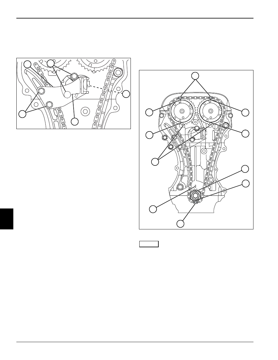
Figure 7-37
NOTES
The crankshaft may need to be rotated several times
before cylinder number one reaches top dead center.
All timing index marks must be aligned simultaneously.
2.
Turn the crankshaft and satisfy the following
conditions to bring number one cylinder to top dead
center.
• Blue timing chain links (2) align with slot/arrow (1) on
cam timing gears.
• Cam timing gear dots (3) align with index marks (8)
on cylinder head.
• Crankshaft timing sprocket keyway (4) faces up and
aligns with index mark (7) on cylinder block.
• Yellow timing chain link (6) aligns with crankshaft
timing gear slot (5).
TN0549
1
2
3
5
4
TN0502
2
1
1
3
3
8
7
5
6
4