Subaru Outback (2019 year). Instruction - part 19
(304,1)
北米Model "A2550BE-A" EDITED: 2018/ 5/ 9
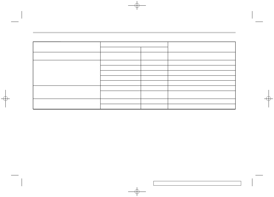
Precondition
Fob Indication
Meaning
Flash
Beep
Fob start button is being pressed
Continuous while button is
held down
—
The fob is transmitting an RF signal
User attempts to start engine by pressing fob
button twice within 3 sec
1 flash
1 beep
Engine start request received
2 flashes
2 beeps
Engine started successfully
1 flash every 3 sec
—
Engine idling
3 flashes
3 beeps
Vehicle is in range but engine not started
2 long flashes
—
Vehicle not in range (engine not started)
Engine idling by remote engine start operation
1 flash every 3 sec
—
Engine idling
3 flashes
3 beeps
Engine stopped by system timeout or for safety
reasons (see sections above)
User attempts to stop engine by pressing and
holding fob button for at least 2 sec.
3 flashes
3 beeps
Engine stopped by user request
1 flash every 3 sec
—
Stop request not received. Engine still idling.
Starting and operating/Remote engine start system (dealer option)
7-18