Subaru Crosstrek (2019 year). Instruction - part 17
(265,1)
北米Model "A1340BE-A" EDITED: 2018/ 4/ 2
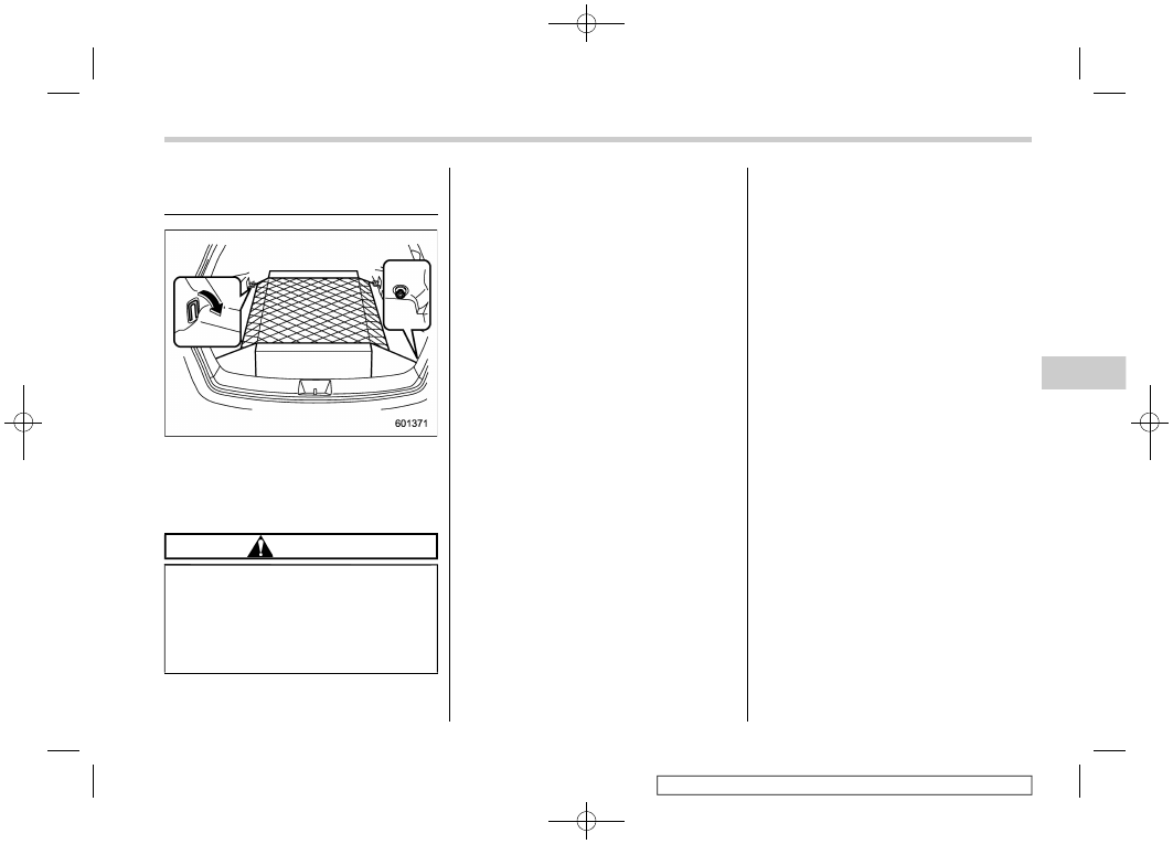
Cargo tie-down hooks
(if equipped)
The cargo area is equipped with two or
four tie-down hooks so that cargo can be
secured with a cargo net or ropes.
When using the front tie-down hooks, turn
them down out of the storing recesses.
CAUTION
The cargo tie-down hooks are de-
signed only for securing light cargo.
Never try to secure cargo that ex-
ceeds the capacity of the hooks. The
maximum load capacity is 22 lbs (10
kg) per hook.
Interior equipment/Cargo tie-down hooks
6-15
6