Subaru Baja (2006 year). Instruction - part 15
6-30
Interior and exterior equipments
2. Raise the cover slightly while holding the key in the
unlock position. After making sure that the cover is
completely unlocked, remove the key from the key cyl-
inder and open the cover slowly to the fully opened po-
sition.
3. When closing the cover, lower the cover until it ap-
proaches approximately 6 in (15 cm) from the closed
position and let it drop. The cover will lock automatical-
ly.
4. After closing the cover, be sure the cover is secure-
ly locked.
If this does not lock the cover, release it from a slightly
higher position. Do not push the cover forcibly to lock
it.
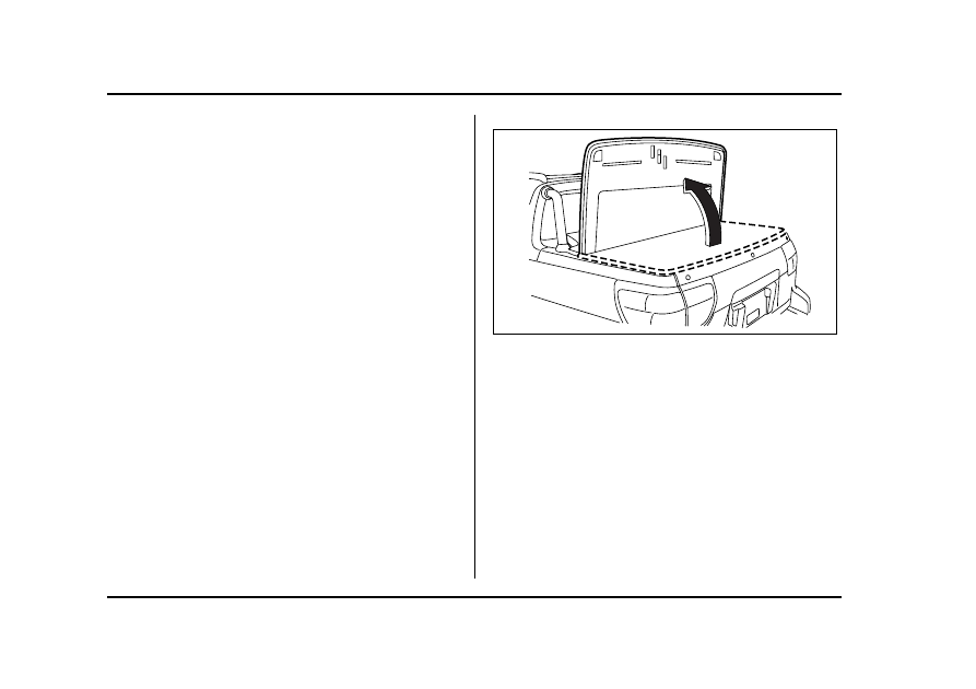
T Rear section
1. Unlock the rear section of the cover. (Refer to
“Locking and unlocking the bed cover” in this section.)
2. Raise the cover slightly while holding the key in the
unlock position. After making sure that the cover is
completely unlocked, remove the key from the key cyl-
inder and open the cover slowly until it contacts the
rear sport bars.
UB6058BA