Subaru Legacy IV (2008 year). Manual - part 987
AC-51
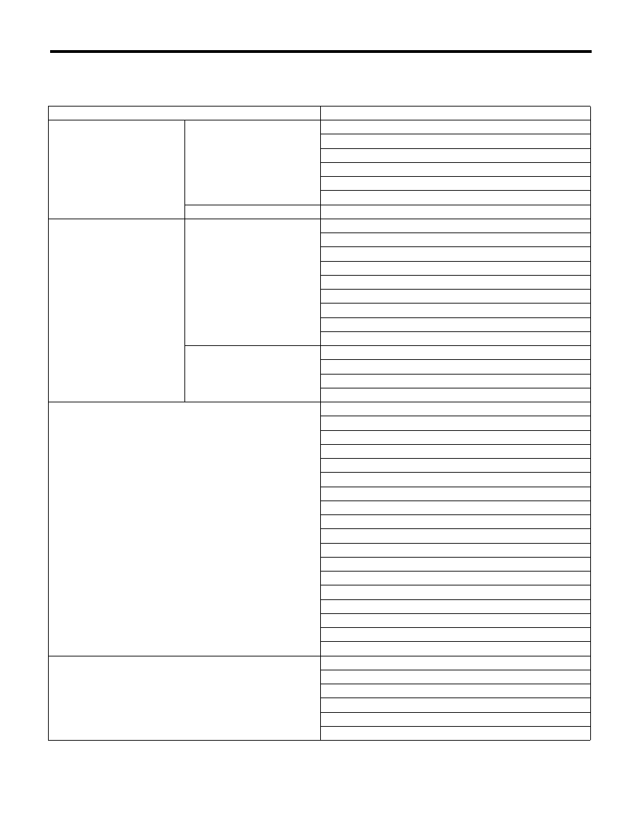
General Diagnostic Table
HVAC SYSTEM (HEATER, VENTILATOR AND A/C)
30.General Diagnostic Table
A: INSPECTION
Symptoms
Repair order
Blower motor
Does not operate.
Fuse
Blower motor relay
Blower motor
Blower motor resistor (Manual A/C)
Blower switch
Wiring harness
Strange noise
Blower motor
Compressor
Does not operate.
Refrigerant
Fuses
Air conditioning relay
Magnet clutch
Compressor
Pressure switch
A/C switch
Blower switch
Wiring harness
Strange noise
V-belt
Magnet clutch
Compressor
Belt tension adjuster
Cold air not emitted.
Refrigerant
V-belt
Magnet clutch
Compressor
Pressure switch
Aspirator hose (Auto A/C)
Blower fan relay
Blower motor
A/C switch
Blower switch
Control module
Expansion valve
Evaporator
Air mix actuator (Auto A/C)
Temperature control cable (Manual A/C)
Wiring harness
Heater duct
Heater vent duct
Warm air not emitted.
Engine coolant
Aspirator hose (Auto A/C)
Air mix actuator (Auto A/C)
Temperature control cable (Manual A/C)
Blower switch
Heater core