Subaru Legacy IV (2008 year). Manual - part 945
VDC(diag)-95
Diagnostic Procedure with Diagnostic Trouble Code (DTC)
VEHICLE DYNAMICS CONTROL (VDC) (DIAGNOSTICS)
2
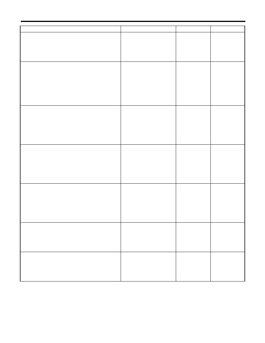
CHECK YAW RATE & LATERAL G SENSOR
GROUND CIRCUIT.
Measure the resistance between the yaw rate &
lateral G sensor and chassis ground.
Connector & terminal
(B230) No. 4 — Chassis ground:
Is the resistance less than 0.5
:? Go to step 3.
Repair the ground
circuit of the yaw
rate & lateral G
sensor.
3
CHECK YAW RATE & LATERAL G SENSOR
HARNESS.
1) Disconnect the connector from the
VDCCM&H/U.
2) Measure the resistance between VDCCM&
H/U and yaw rate & lateral G sensor.
Connector & terminal
(B230) No. 3 — (B310) No. 10:
(B230) No. 2 — (B310) No. 35:
Is the resistance less than 0.5
:? Go to step 4.
Repair the harness
between yaw rate
& lateral G sensor
and VDCCM& H/U.
4
CHECK GROUND SHORT CIRCUIT FOR
YAW RATE & LATERAL G SENSOR HAR-
NESS.
Measure the resistance between the yaw rate &
lateral G sensor and chassis ground.
Connector & terminal
(B230) No. 2 — Chassis ground:
(B230) No. 3 — Chassis ground:
Is the resistance 1 M
: or
more?
Go to step 5.
Repair the harness
between yaw rate
& lateral G sensor
and VDCCM& H/U.
5
CHECK YAW RATE & LATERAL G SENSOR.
1) Turn the ignition switch to OFF.
2) Connect all connectors.
3) Clear the memory. <Ref. to VDC(diag)-23,
Clear Memory Mode.>
4) Perform the Inspection Mode. <Ref. to
VDC(diag)-22, Inspection Mode.>
5) Read the DTC.
Is the same DTC displayed?
Go to step 6.
Go to step 7.
6
CHECK YAW RATE & LATERAL G SENSOR.
1) Turn the ignition switch to OFF.
2) Replace the yaw rate & lateral G sensor.
3) Clear the memory. <Ref. to VDC(diag)-23,
Clear Memory Mode.>
4) Perform the Inspection Mode. <Ref. to
VDC(diag)-22, Inspection Mode.>
5) Read the DTC.
Is the same DTC displayed?
Replace the
VDCCM only.
<Ref. to VDC-10,
REPLACEMENT,
VDC Control Mod-
ule and Hydraulic
Control Unit
(VDCCM&H/U).>
Go to step 8.
7
CHECK OTHER DTC DETECTION.
Is any other DTC displayed?
Perform the diag-
nosis according to
DTC. <Ref. to
VDC(diag)-34, List
of Diagnostic Trou-
ble Code (DTC).>
Temporary poor
contact occurs.
8
CHECK OTHER DTC DETECTION.
Is any other DTC displayed?
Perform the diag-
nosis according to
DTC. <Ref. to
VDC(diag)-34, List
of Diagnostic Trou-
ble Code (DTC).>
Malfunction is
found in original
yaw rate & lateral
G sensor.
Step
Check
Yes
No