Subaru Legacy IV (2008 year). Manual - part 938
VDC(diag)-67
Diagnostic Procedure with Diagnostic Trouble Code (DTC)
VEHICLE DYNAMICS CONTROL (VDC) (DIAGNOSTICS)
AF:DTC C0052 MOTOR AND MOTOR RELAY ON FAILURE
DTC DETECTING CONDITION:
• Defective motor relay
• Defective harness connector
TROUBLE SYMPTOM:
• ABS does not operate.
• VDC does not operate.
• EBD may not operate.
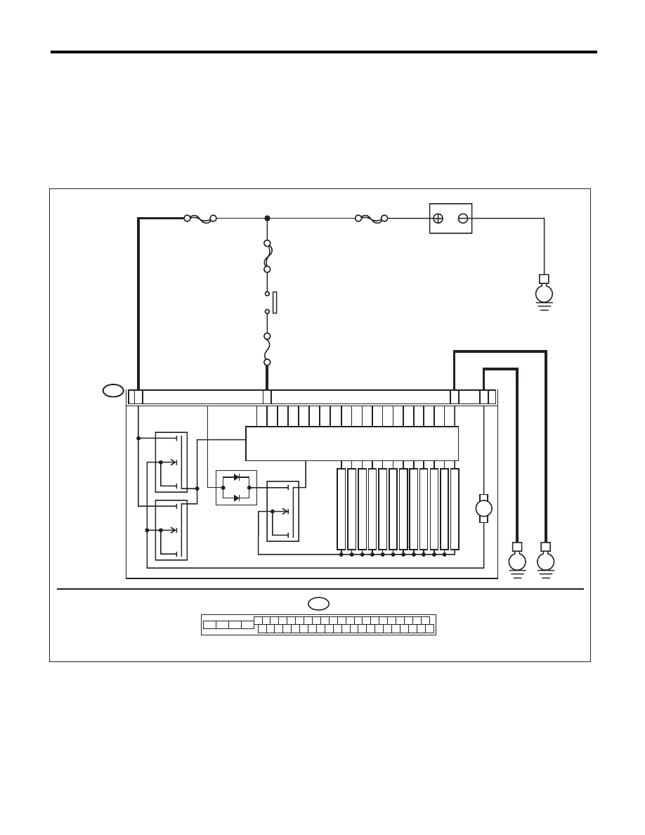
WIRING DIAGRAM:
B310
E
23
25
VDCCM & H/U
28
PUMP MOTOR
M
FL INLET
MAIN SBF
SBF-6
No.33
E
BATTERY
IGNITION
SWITCH
SOLENOID VALVE
MOTOR RELAY
VALVE RELAY
FR INLET
RL INLET
RR INLET
FL OUTLET
FR OUTLET
RL OUTLET
RR OUTLET
PRIMARY CUT
SECONDARY CUT
PRIMARY SUCTION
SBF-1
E
22
SECONDARY SUCTION
B310
4 5 6 7 8 9
26 27 28 29 30
2 3
1
31 32 33 34 35 36
10 11
14 15 16 17 18 19
37 38 39 40
12 13
41 42 43 44 45 46
20 21
23
24
22
25
VDC00467