Subaru Legacy IV (2008 year). Manual - part 929
VDC(diag)-31
Warning Light Illumination Pattern
VEHICLE DYNAMICS CONTROL (VDC) (DIAGNOSTICS)
F: VDC WARNING LIGHT AND VDC OFF INDICATOR LIGHT DO NOT GO OFF
DETECTING CONDITION:
• Defective combination meter
• Defective CAN communication
• Defective engine
• VDC OFF switch is shorted.
TROUBLE SYMPTOM:
When starting the engine, VDC OFF indicator light is kept ON.
NOTE:
When pressing the VDC OFF switch for 10 seconds or more, the VDC OFF indicator light goes off and cannot
operate any more. When turning the ignition switch from OFF to ON, the OFF operation enabled status is re-
stored.
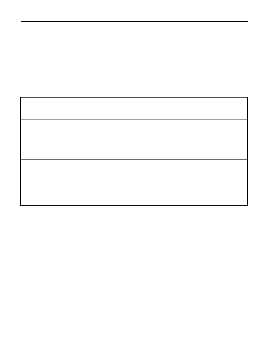
Step
Check
Yes
No
1
READ DTC.
Read the DTC. <Ref. to VDC(diag)-21, Read
Diagnostic Trouble Code (DTC).>
Is DTC displayed?
Perform the diag-
nosis according to
DTC.
Go to step 2.
2
CHECK ENGINE.
Does the malfunction indicator
light illuminate?
Repair the engine. Go to step 3.
3
CHECK ENGINE COOLANT TEMPERA-
TURE.
Warm up the engine and check if VDC warning
light and VDC OFF indicator light illumination
condition changes.
When the engine coolant tem-
perature is too low, VDC warn-
ing light and VDC OFF indicator
light illuminate. Do the lights go
off when the engine is warmed
up?
Normal operation
Go to step 4.
4
CHECK VDC OFF SWITCH.
Remove and check VDC OFF switch. <Ref. to
VDC-24, VDC OFF Switch.>
Is the VDC OFF switch normal? Go to step 5.
Replace the VDC
OFF switch.
5
CHECK LAN SYSTEM.
Perform the diagnosis for LAN system. <Ref. to
LAN(diag)-27, OPERATION, Read Diagnostic
Trouble Code (DTC).>
Is there any fault in LAN sys-
tem?
Perform the diag-
nosis according to
DTC for LAN sys-
tem.
Go to step 6.
6
CHECK COMBINATION METER.
Check the combination meter.
Is combination meter OK?
Replace the
VDCCM only.
Repair the combi-
nation meter.