Subaru Legacy IV (2008 year). Manual - part 924
VDC(diag)-11
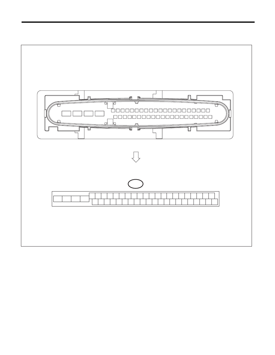
Control Module I/O Signal
VEHICLE DYNAMICS CONTROL (VDC) (DIAGNOSTICS)
5. Control Module I/O Signal
A: ELECTRICAL SPECIFICATION
NOTE:
• Terminal numbers in VDCCM&H/U connector are shown in the figure.
• When the connector is removed from VDCCM&H/U, the ABS warning light, VDC warning light and VDC
OFF indicator light illuminate.
VDC00457
B310
4 5 6 7 8 9
26 27 28 29 30
2 3
1
31 32 33 34 35 36
10 11
14 15 16 17 18 19
37 38 39 40
12 13
41 42 43 44 45 46
20 21
23
24
22
25