Subaru Legacy IV (2008 year). Manual - part 846
RS-6
General Description
REAR SUSPENSION
2. GENERAL TOOL
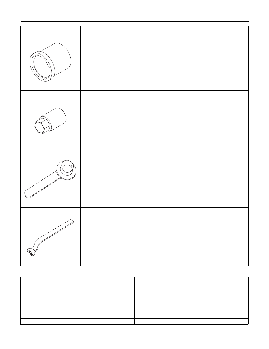
20099AE030
HELPER SOCKET
WRENCH
Used for replacing helper.
20399AG000
STRUT MOUNT
SOCKET
Used for removing and installing shock mount.
28099PA090
OIL SEAL
PROTECTOR
• Used for installing the rear drive shaft to the
rear differential.
• For oil seal protection
28099PA100
REMOVER
Used for removal of DOJ.
TOOL NAME
REMARKS
Alignment gauge
Used for measuring wheel alignment.
Alignment gauge adapter
Used for measuring wheel alignment.
Turning radius gauge
Used for measuring wheel alignment.
Toe-in gauge
Used for toe-in measurement.
Transmission jack
Used for removing and installing suspension.
Bearing puller
Used for removing bushings.
Coil spring compressor
Used for disassembling and assembling shock absorber.
ILLUSTRATION
TOOL NUMBER
DESCRIPTION
REMARKS
ST20099AE030
ST20399AG000
ST28099PA090
ST28099PA100