Subaru Legacy IV (2008 year). Manual - part 836


  Index      Subaru     Subaru Legacy IV - service repair manual 2008 year


Search            


Content   ..  834  835  836  837   ..


Subaru Legacy IV (2008 year). Manual - part 836


CL-30

Clutch Fluid Air Bleeding

CLUTCH SYSTEM

9. Clutch Fluid Air Bleeding

A: PROCEDURE

1. 5MT MODEL

NOTE:
Bleed air from the oil line with help of a co-worker.
1) Remove the air intake chamber. (Non-turbo
model) <Ref. to IN(H4SO)-7, REMOVAL, Air Intake
Chamber.>
2) Remove the intercooler. (Turbo model) <Ref. to
IN(H4DOTC)-12, REMOVAL, Intercooler.>
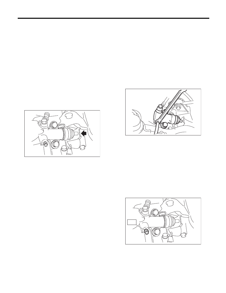
3) Fit one end of a vinyl tube into the air bleeder of
the operating cylinder, and put the other end into a
brake fluid container.

NOTE:
The illustration below is for a Non-turbo model.
However, perform the same procedures for the
Turbo model.

4) Slowly depress the clutch pedal and keep it de-
pressed. Then open the air bleeder to discharge air
together with the fluid.
Release the air bleeder for 1 or 2 seconds. Next,
with the bleeder closed, slowly release the clutch
pedal.

CAUTION:
Cover the bleeder with cloth to prevent brake
fluid from being splashed on surrounding parts
when loosening the bleeder.

NOTE:
The illustration below is for a Non-turbo model.
However, perform the same procedures for the
Turbo model.

5) Repeat procedure 4), until there are no more air
bubbles in the vinyl tube.
6) Tighten the air bleeder.

Tightening torque:

T: 7.8 N·m (0.8 kgf-m, 5.8 ft-lb)

NOTE:
The illustration below is for a Non-turbo model.
However, perform the same procedures for the
Turbo model.

7) After stepping on the clutch pedal, make sure
that there are no leaks evident in the entire clutch
system.
8) After bleeding the air from clutch system, ensure
that the clutch operates properly.

(A) Clutch hose

(B) Air bleeder

CL-00369

(A)

(B)

(A) Operating cylinder

(B) Vinyl tube

CL-00370

(B)

(A)

CL-00372

T

CL-31

Clutch Fluid Air Bleeding

CLUTCH SYSTEM

9) Install the air intake chamber. (Non-turbo model)
<Ref. to IN(H4SO)-7, INSTALLATION, Air Intake
Chamber.>
10) Install the intercooler. (Turbo model) <Ref. to
IN(H4DOTC)-13, INSTALLATION, Intercooler.>

2. 6MT MODEL

NOTE:
Bleed air from the oil line with help of a co-worker.
1) Remove the intercooler. <Ref. to IN(H4DOTC)-
12, REMOVAL, Intercooler.>
2) Fit one end of a vinyl tube to the air bleeder of
the master cylinder, and put the other end into a
brake fluid container.
3) Remove the operating cylinder.

NOTE:
Do not remove the clutch hose.

4) Hold the piston with a clamp to prevent piston
from popping out.

5) Fit one end of a vinyl tube into the air bleeder of
the operating cylinder, and put the other end into a
brake fluid container.

6) Slowly depress the clutch pedal and keep it de-
pressed. Then open the air bleeder to discharge air
together with the fluid.
Release the air bleeder for 1 or 2 seconds. Next,
with the bleeder closed, slowly release the clutch
pedal.

NOTE:
When performing this procedure, place the screw
portion of the air bleeder higher than the end of op-
erating cylinder.

7) Repeat these steps until there are no more air
bubbles in the vinyl tube.

CAUTION:
Cover the bleeder with cloth to prevent brake
fluid from being splashed on surrounding parts
when loosening the bleeder.
8) Tighten the air bleeder.

Tightening torque:

7.8 N·m (0.8 kgf-m, 5.8 ft-lb)

9) Install the operating cylinder.

Tightening torque:

41 N·m (4.2 kgf-m, 30.2 ft-lb)

10) After depressing the clutch pedal, make sure
that there are no leaks evident in the entire system.
11) After bleeding air from system, ensure that the
clutch operates properly.
12) Install the intercooler. <Ref. to IN(H4DOTC)-
13, INSTALLATION, Intercooler.>

CL-00445

CL-00446

(A) Operating cylinder

(B) Vinyl tube

CL-00447

(B)

(A)

CL-00445

CL-32

Clutch Pedal

CLUTCH SYSTEM

10.Clutch Pedal

A: REMOVAL

1) Disconnect the ground cable from battery.
2) Remove the steering column. <Ref. to PS-16,
REMOVAL, Tilt Steering Column.>
3) Disconnect the connectors of the stop light
switch and clutch switch.
4) Remove the snap pins from clevis pins which se-
cure the lever to the push rod and operating rod.
5) Pull out the clevis pins which secures the lever to
the push rod and operating rod.

6) Remove the air intake chamber. (Non-turbo
model) <Ref. to IN(H4SO)-7, REMOVAL, Air Intake
Chamber.>
7) Remove the intercooler. (Turbo model) <Ref. to
IN(H4DOTC)-12, REMOVAL, Intercooler.>
8) Remove the nut which secures the clutch master
cylinder.

9) Remove the bolt which secures the brake pedal
and clutch pedal, and remove the pedal assembly.

B: INSTALLATION

1) Install in the reverse order of removal.

Tightening torque:

T: 18 N·m (1.8 kgf-m, 13.3 ft-lb)

CAUTION:
Always use a new clevis pin.
2) Adjust the clutch pedal after installation. <Ref. to
CL-34, ADJUSTMENT, Clutch Pedal.>

C: DISASSEMBLY

1) Remove the clutch switches.
2) Remove the clip, assist spring, rod and bushing.

3) Extract the spring pin and remove the lever.

(A) Operating rod

(B) Push rod

(C) Snap pin

(D) Clevis pin

(D)

(B)

(C)

(C)

(D)

(A)

CL-00292

CL-00093

(A) Clip

(B) Assist spring

(C) Assist rod

(D) Bushing

(E) Clevis pin

(A) Pin

(B) Lever

CL-00573

(A)

(B)

(C)

(C)

(D)

(D)

(D)

(E)

(E)

CL-00095

(A)

(B)

CL-33

Clutch Pedal

CLUTCH SYSTEM

4) Remove the clutch pedal and bushing.

5) Remove the stopper from the clutch pedal.

6) Remove the clutch pedal pad.

D: ASSEMBLY

1) Temporarily assemble the clutch switch, etc. to
pedal bracket.
2) Clean the clutch pedal and brake pedal bushing
holes, apply a thin coat of grease, and install the
bushings.
3) Align the holes of the pedal bracket, clutch pedal
and brake pedal, and install the brake pedal return
spring, assist rod, spring and bushing.

NOTE:
Clean the inside of bushings and apply a thin coat
of grease before installing the spacer.

E: INSPECTION

1. CLUTCH PEDAL

Move the clutch pedal pads in the lateral direction
with a force of approximately 10 N (1 kgf, 2 lbf) to
check that the clutch pedal deflection is within the
service limit.
If it exceeds the service limit, replace with new
bushings.

Deflection of the clutch pedal:

Service limit

4.0 mm (0.157 in) or less

(A) Clutch pedal

(B) Bushing

(A) Stopper

(A)

(B)

(B)

CL-00574

(A)

CL-00535

(A) Clutch pedal

(B) Brake pedal

CL-00098

(A)

(B)


Content   ..  834  835  836  837   ..