Subaru Legacy IV (2008 year). Manual - part 814
6MT-69
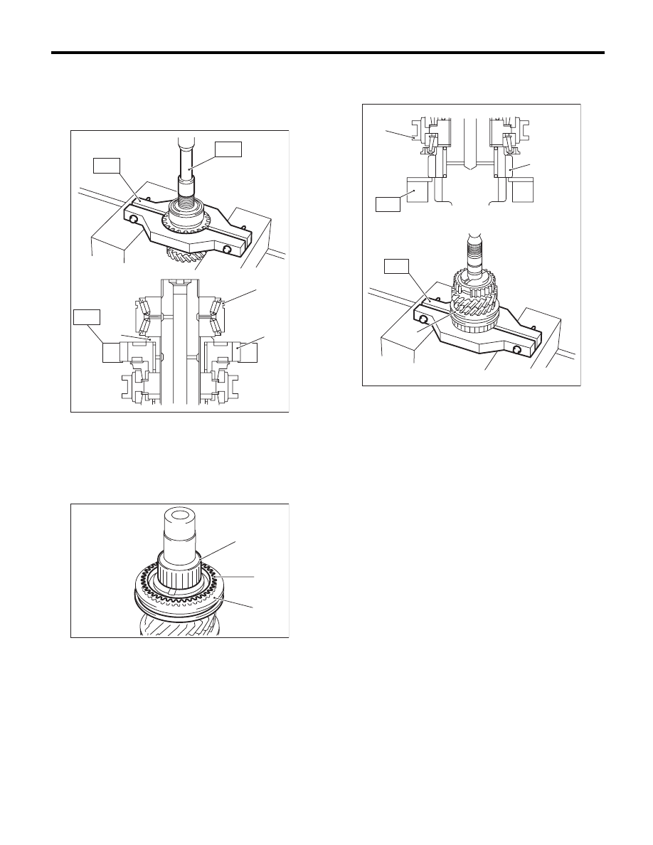
Main Shaft Assembly
MANUAL TRANSMISSION AND DIFFERENTIAL
5) Set the ST1 to the 6th drive gear, and use a
press to remove the taper roller bearing, bushing
and 6th drive gear.
ST1
18722AA010
REMOVER
ST2
899864100
REMOVER
6) Remove the 5th-6th sleeve, 6th needle bearing
and 6th baulk ring.
7) Set the ST to the 3rd drive gear, and use a press
to remove individual parts.
ST
18720AA000
REMOVER
(A) Taper roller bearing
(B) Bushing
(C) 6th drive gear
(A) Needle bearing
(B) 6th baulk ring
(C) 5th-6th sleeve
MT-00557
(A)
(B)
(C)
ST1
ST2
ST1
(A)
(B)
(C)
MT-00558
(A) 3rd drive gear
(B) 3rd-4th sleeve
(A)
ST
(B)
(B)
ST
MT-01406