Subaru Legacy IV (2008 year). Manual - part 805


  Index      Subaru     Subaru Legacy IV - service repair manual 2008 year


Search            


Content   ..  803  804  805  806   ..


Subaru Legacy IV (2008 year). Manual - part 805


6MT-33

Manual Transmission Assembly

MANUAL TRANSMISSION AND DIFFERENTIAL

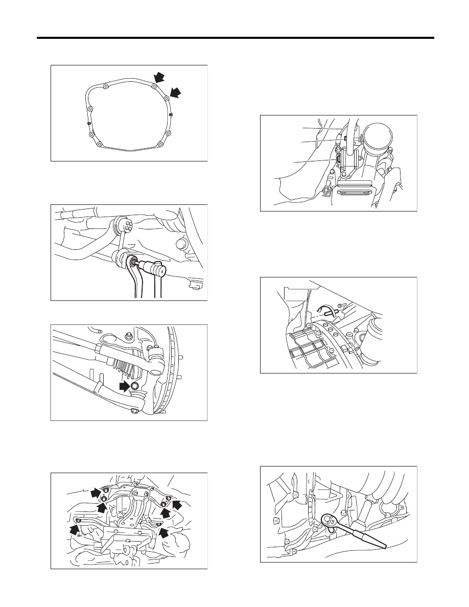
16) Remove the bolts which hold upper side of
transmission to engine.

17) Remove the heat shield cover. (If equipped)
18) Remove the propeller shaft. <Ref. to DS-10,
REMOVAL, Propeller Shaft.>
19) Remove the front stabilizer link.

20) Remove the ball joint of front arm from the
housing.

21) Remove the front drive shaft. <Ref. to DS-22,
REMOVAL, Front Drive Shaft.>
22) Set the transmission jack under the transmis-
sion, and remove the front crossmember and rear
crossmember.

23) Move the transmission to the right side of the
vehicle, and remove the joint COMPL, stay bolts
and reverse check cable.

NOTE:
If the transmission is not moved aside, the joint
COMPL and stay bolts may contact the body and
cause damage.

24) Tighten the turnbuckle of the ST to tilt the en-
gine assembly towards the back.

25) Remove the bolts and nuts holding the bottom
of transmission to the engine, and remove the
transmission from the vehicle.

NOTE:
• During removal, be careful not to hit the trans-
mission against the body when pulling towards the
rear.
• The clutch pipe and breather pipe may interfere
with each other. Remove carefully.

MT-01524

FS-00117

FS-00106

MT-01264

(A) Joint COMPL bolt

(B) Stay bolt

(C) Reverse check cable

MT-00886

(C)

(A)

(B)

MT-00463

MT-01090

6MT-34

Manual Transmission Assembly

MANUAL TRANSMISSION AND DIFFERENTIAL

B: INSTALLATION

1) Set the release fork, release bearing and release
shaft to the transmission. <Ref. to CL-19, INSTAL-
LATION, Release Bearing and Lever.>
2) Replace the front differential side retainer oil
seal.

(1) Remove the oil seal by using flat tip screw-
driver etc.
(2) Apply gear oil to the lip of new oil seals.
(3) Install a new oil seal using ST.

ST

18675AA000

DIFFERENTIAL SIDE OIL 
SEAL INSTALLER

NOTE:
Be sure to replace the differential side oil seal after
the procedure of removing front drive shaft from
transmission.
3) Loosen the turnbuckle of ST to return the engine
to its original position.

4) Install the transmission.
5) Tighten the bolts and nuts which hold the lower
side of the transmission to the engine.

NOTE:
• Make sure that the main shaft spline is complete-
ly inserted.
• Make sure that the rear end of the engine is set
low.

Tightening torque:

50 N·m (5.1 kgf-m, 36.9 ft-lb)

6) Move the transmission to the right side of the ve-
hicle, and attach the joint COMPL, stay bolts and
reverse check cable.

Tightening torque:

T1: 11.8 N·m (1.2 kgf-m, 8.7 ft-lb)
T2: 32 N·m (3.3 kgf-m, 23.6 ft-lb)

7) Install the front crossmember and rear cross-
member.

Tightening torque:

T1: 75 N·m (7.6 kgf-m, 55.3 ft-lb)
T2: 140 N·m (14.3 kgf-m, 103.3 ft-lb)

8) Tighten the bolts which the hold upper side of
the transmission to the engine.

Tightening torque:

50 N·m (5.1 kgf-m, 36.9 ft-lb)

MT-01527

MT-00464

(A) Reverse check cable

MT-00465

(A)

T2

T1

MT-01265

T1

T2

T2

T1

MT-01524

6MT-35

Manual Transmission Assembly

MANUAL TRANSMISSION AND DIFFERENTIAL

9) Make sure that the release bearing is completely
inserted.

NOTE:
• Push the release fork towards the operating cyl-
inder side until a clicking sound is heard. Pull the
release fork towards the engine side. If the release
fork is not in contact with the case, the setting is
complete.
• Confirm that the boot cover is set securely.

10) Install the pitching stopper bracket.

Tightening torque:

41 N·m (4.2 kgf-m, 30.2 ft-lb)

11) Install the pitching stopper.

Tightening torque:

T1: 50 N·m (5.1 kgf-m, 36.9 ft-lb)
T2: 58 N·m (5.9 kgf-m, 42.8 ft-lb)

12) Install the clutch operating cylinder.

Tightening torque:

41 N·m (4.2 kgf-m, 30.2 ft-lb)

NOTE:
Check that the clutch hose is routed properly.

13) Install the starter assembly. <Ref. to
SC(H4SO)-6, INSTALLATION, Starter.>
14) Attach the ground cable to the transmission
and body.

15) Connect the following harness connectors,
then attach the engine hanger rear.

16) Set the ST to side retainer.
ST

28399SA010

OIL SEAL PROTECTOR

17) Install the front drive shaft into the transmis-
sion.

NOTE:
Replace the circlip of drive shaft with a new part.
18) Install the front drive shaft into transmission, re-
move the ST and insert the drive shaft securely.
ST

28399SA010

OIL SEAL PROTECTOR

MT-00467

MT-01560

T1

T2

CL-00445

(A) Neutral position switch backup light switch con-

nector

(B) Rear oxygen sensor connector

(C) Pitching stopper

MT-01266

MT-01267

MT-01540

(A)

(B)

(C)

6MT-36

Manual Transmission Assembly

MANUAL TRANSMISSION AND DIFFERENTIAL

19) Install the ball joint of the front arm.

Tightening torque:

50 N·m (5.1 kgf-m, 36.9 ft-lb)

20) Install the front stabilizer link.

Tightening torque:

45 N·m (4.6 kgf-m, 33.2 ft-lb)

NOTE:
Use a new self-locking nut.

21) Install the heat shield cover. (If equipped)
22) Install the propeller shaft. <Ref. to DS-11, IN-
STALLATION, Propeller Shaft.>
23) Install the rear exhaust pipe and muffler. <Ref.
to EX(H4DOTC)-13, INSTALLATION, Rear Ex-
haust Pipe.> <Ref. to EX(H4DOTC)-14, INSTAL-
LATION, Muffler.>
24) Install the center exhaust pipe. <Ref. to
EX(H4DOTC)-9, INSTALLATION, Center Exhaust
Pipe.>
25) Fill the transmission gear oil.
<Ref. to 6MT-27, REPLACEMENT, Transmission
Gear Oil.>
26) Install the intercooler. <Ref. to IN(H4DOTC)-
13, INSTALLATION, Intercooler.>
27) Install the collector cover.
28) Connect the ground cable to battery.

FS-00106

FS-00117


Content   ..  803  804  805  806   ..