Subaru Legacy IV (2008 year). Manual - part 786


  Index      Subaru     Subaru Legacy IV - service repair manual 2008 year


Search            


Content   ..  784  785  786  787   ..


Subaru Legacy IV (2008 year). Manual - part 786


5MT-40

Transfer Case and Extension Case Assembly

MANUAL TRANSMISSION AND DIFFERENTIAL

13) Select a suitable washer in the following table.

Standard clearance:

0.15 — 0.35 mm (0.0059 — 0.0138 in)

14) Fit the thrust washer onto the center differen-
tial.
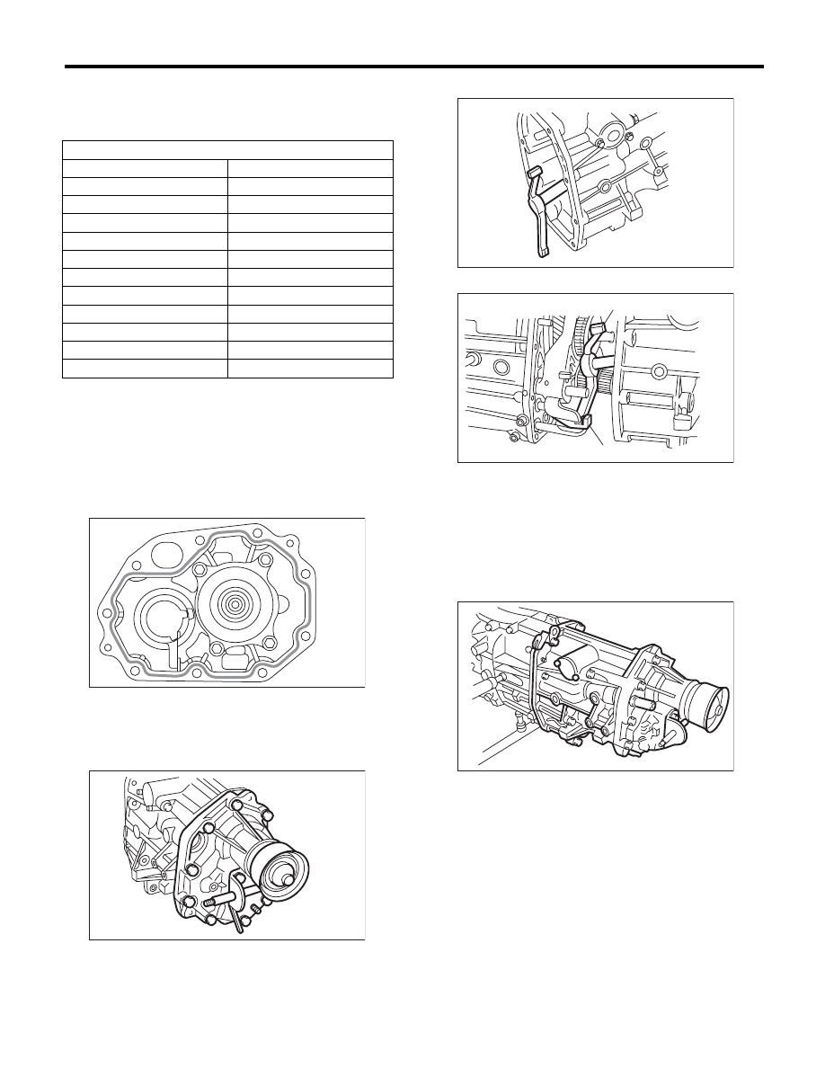
15) Apply a proper amount of liquid gasket to the
transfer case mating surface.

Liquid gasket:

THREE BOND 1215 (Part No. 004403007) or 
equivalent

16) Install the extension assembly into the transfer
case.

Tightening torque:

40 N·m (4.1 kgf-m, 29.5 ft-lb)

17) Attach the shifter arm to transfer case.

18) Hang the shifter arm on 3rd-4th fork rod.

19) Install the extension case assembly along with
the transfer case to the transmission case.

Tightening torque:

24.5 N·m (2.5 kgf-m, 18.1 ft-lb)

Thrust washer

Part number

Thickness mm (in)

803036050

0.9 (0.035)

803036054

1.0 (0.039)

803036051

1.1 (0.043)

803036055

1.2 (0.047)

803036052

1.3 (0.051)

803036056

1.4 (0.055)

803036053

1.5 (0.059)

803036057

1.6 (0.063)

803036058

1.7 (0.067)

803036080

1.8 (0.071)

803036081

1.9 (0.075)

MT-00124

MT-00117

(A) Shifter arm

(B) 3rd-4th fork rod

MT-00126

MT-00127

(A)

(B)

MT-00116

5MT-41

Transfer Case and Extension Case Assembly

MANUAL TRANSMISSION AND DIFFERENTIAL

C: DISASSEMBLY

1. TRANSFER CASE

1) Remove the reverse check assembly. <Ref. to
5MT-47, REMOVAL, Reverse Check Sleeve.>
2) Remove the oil guide.

2. EXTENSION CASE

1) Remove the transfer drive gear assembly. <Ref.
to 5MT-42, REMOVAL, Transfer Drive Gear.>
2) Remove the shift bracket.

3) Remove the oil seal from the extension case.
<Ref. to 5MT-33, Oil Seal.>

D: ASSEMBLY

1. EXTENSION CASE

1) Using the ST, install the oil seal to the extension
case. <Ref. to 5MT-33, Oil Seal.>

NOTE:
Use a new oil seal.
2) Install the shift bracket to extension case.

Tightening torque:

24.5 N·m (2.5 kgf-m, 18.1 ft-lb)

3) Install the transfer drive gear to the extension
case. <Ref. to 5MT-42, INSTALLATION, Transfer
Drive Gear.>

2. TRANSFER CASE

1) Install the oil guide to the transfer case.

Tightening torque:

6.4 N·m (0.7 kgf-m, 4.7 ft-lb)

NOTE:
Use a new installing bolt.

2) Install the reverse check sleeve assembly to the
transfer case. <Ref. to 5MT-47, INSTALLATION,
Reverse Check Sleeve.>

MT-01563

MT-00130

MT-00130

MT-01563

5MT-42

Transfer Drive Gear

MANUAL TRANSMISSION AND DIFFERENTIAL

10.Transfer Drive Gear

A: REMOVAL

1) Remove the manual transmission assembly
from the vehicle. <Ref. to 5MT-24, REMOVAL,
Manual Transmission Assembly.>
2) Remove the back-up light switch neutral position
switch. <Ref. to 5MT-35, REMOVAL, Switches and
Harness.>
3) Remove the transfer case together with the ex-
tension case assembly. <Ref. to 5MT-38, REMOV-
AL, Transfer Case and Extension Case
Assembly.>
4) Remove the extension case assembly.
5) Remove the transfer driven gear. <Ref. to 5MT-
44, REMOVAL, Transfer Driven Gear.>
6) Remove the transfer drive gear. 

B: INSTALLATION

1) Attach the transfer drive gear.

Tightening torque:

26 N·m (2.7 kgf-m, 19.2 ft-lb)

2) Install the transfer driven gear. <Ref. to 5MT-44,
INSTALLATION, Transfer Driven Gear.>
3) Install the extension case assembly.
4) Install the transfer case and the extension case
assembly. <Ref. to 5MT-38, INSTALLATION,
Transfer Case and Extension Case Assembly.>
5) Install the back-up light switch neutral position
switch. <Ref. to 5MT-35, INSTALLATION, Switch-
es and Harness.>
6) Install the manual transmission assembly to the
vehicle. <Ref. to 5MT-27, INSTALLATION, Manual
Transmission Assembly.>

C: DISASSEMBLY

1) Remove the snap ring.

2) Remove the ball bearing.

D: ASSEMBLY

1) Set the ST against the inner race of the bearing,
and install the drive shaft.
ST

398177700

INSTALLER

CAUTION:
Do not apply pressure in excess of 10 kN (1 ton,
1.1 US ton, 1.0 Imp ton).

2) Install the snap ring on the transfer drive shaft.
3) Inspect the clearance between the snap ring and
the ball bearing. <Ref. to 5MT-43, INSPECTION,
Transfer Drive Gear.>

MT-00133

MT-00133

MT-00135

MT-00136

MT-00137

ST

5MT-43

Transfer Drive Gear

MANUAL TRANSMISSION AND DIFFERENTIAL

E: INSPECTION

1) Bearing
Replace the bearings in the following cases.
• In case of broken or rusty bearings
• In case of worn or damaged bearings
• When the bearings fail to turn smoothly or emit
noise in rotation after gear oil lubrication.
2) Drive gear
If the drive gear tooth surface and shaft are exces-
sively broken or damaged, replace the drive gear.
3) Measure the clearance between snap ring and
inner race of ball bearing with a thickness gauge.

Clearance:

0.01 — 0.15 mm (0.0004 — 0.0059 in)

If the measurement is not within specification, se-
lect a suitable snap ring and replace it.

Snap ring (Outer-30)

Part number

Thickness mm (in)

805030041

1.53 (0.0602)

805030042

1.65 (0.0650)

805030043

1.77 (0.0697)

MT-00138


Content   ..  784  785  786  787   ..