Subaru Legacy IV (2008 year). Manual - part 772


  Index      Subaru     Subaru Legacy IV - service repair manual 2008 year


Search            


Content   ..  770  771  772  773   ..


Subaru Legacy IV (2008 year). Manual - part 772


5AT(diag)-103

Diagnostic Procedure with Diagnostic Trouble Code (DTC)

AUTOMATIC TRANSMISSION (DIAGNOSTICS)

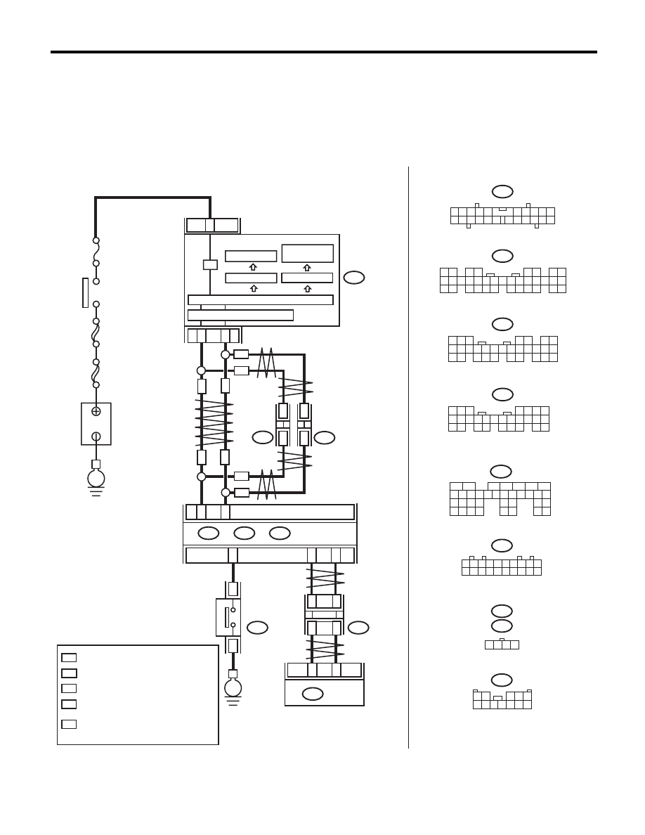
AL:DTC P1817 SPORT MODE SWITCH CIRCUIT (MANUAL SWITCH)

DTC DETECTING CONDITION:
Input signal circuit of SPORT/manual mode switch is open or shorted.
TROUBLE SYMPTOM:
• Manual mode can not be set.
• When shifting to “N” 

o “D”, the SPORT shift indicator light illuminates.

WIRING DIAGRAM:

AT-04895

3

21

22

i10

i84

A:

B280

B:

A26

A27

B20

B30

21

20

TCM

B55

i10

i84

B280

2

1

3 4

6 7 8 9 10

22

21

20

19

18

17

16

15

14

13

12

11

5

8

7

6

5

4

3

2

1

22 23

21

20

19

16

15

14

13

12

11

10

9

34 35

33

32

17
30

18
31

29

28

27

26

25

24

8

7

6

5

4

3

2

1

22

23

21

20

19

16

15

14

13

12

11

10

9

17

30

18

29

28

27

26

25

24

A:

B:

B365

i107

i106

1 2 3 4 5 6 7 8 9 10

11 12 13 14 15 16 17 18 19 20

1

*

2

*

1

*

2

*

 :

 :

1

*

2

*

 :

*

1 2 3 4

MAIN  SBF

SBF-6

No.

 5

E

B365

B55

5

6

7

8

2

1

9

4

3

10

24

22 23

25

11 12 13 14 15

26 27

28

16 17 18 19

20 21

29 30 31

32 33

34 35

 :

WN

 :

ON

WN

WN

ON

i107

i106

*

*

*

*

ON

WN

WN

ON

ON

C26

B116

8

9

E

B116

1 2

3 4 5

6 7 8 9 10 11 12

LCD DRIVER

LCD (AT / 
SPORT SHIFT)

B281

C:

B281

8

7

6

5

4

3

2

1

22 23

21

20

19

16

15

14

13

12

11

10

9

17 18

28

27

26

25

24

C:

WITH NAVIGATION

WITHOUT NAVIGATION

TERMINAL No. OPTIONAL ARRANGEMENT
AMONG 1, 2, 3, 11, 12 AND 13

TERMINAL No. OPTIONAL ARRANGEMENT

TERMINAL No. OPTIONAL ARRANGEMENT
AMONG 8, 9, 10, 18, 19 AND 20

COMBINATION
METER

BODY

INTEGRATED UNIT

IGNITION

SWITCH

B

A

TTER

Y

CAN
JOINT
CONNECTOR

CAN
JOINT
CONNECTOR

CAN TRANSCEIVER  &  RECEIVER

MICRO COMPUTER

LCD FULL DOT

AT
SELECT
LEVER

DRIVE CIRCUIT

CAN

JOINT

CONNECTOR

5AT(diag)-104

Diagnostic Procedure with Diagnostic Trouble Code (DTC)

AUTOMATIC TRANSMISSION (DIAGNOSTICS)

Step

Check

Yes

No

1

CHECK BODY INTEGRATED UNIT.
1) Connect the Subaru Select Monitor to data 
link connector.
2) Turn the ignition switch to ON. (engine OFF)
3) Read the DTC of body integrated unit using 
Subaru Select Monitor. <Ref. to LAN(diag)-12, 
OPERATION, Subaru Select Monitor.>

Is DTC displayed?

Perform the diag-
nosis according to 
DTC.

Go to step 2.

2

CHECK BODY INTEGRATED UNIT INPUT 
SIGNAL.
1) Shift the AT select lever to “P” range.
2) Read the "Tiptronic Mode Switch" data of 
the body integrated unit using the Subaru 
Select Monitor. <Ref. to LAN(diag)-12, OPERA-
TION, Subaru Select Monitor.>

Is OFF displayed?

Go to step 3.

Go to step 7.

3

CHECK BODY INTEGRATED UNIT INPUT 
SIGNAL.
1) Shift the AT select lever from “P” to “D” 
range.
2) Read the "Tiptronic Mode Switch" data of 
the body integrated unit using the Subaru 
Select Monitor. <Ref. to LAN(diag)-12, OPERA-
TION, Subaru Select Monitor.>

Is the indication on each range 
OFF?

Go to step 4.

Replace the select 
lever assembly. 
<Ref. to CS-23, 
Select Lever.>

4

CHECK BODY INTEGRATED UNIT INPUT 
SIGNAL.
1) Shift the AT select lever to manual mode.
2) Shift the AT select lever to other than “D” 
range.
3) Read the "Tiptronic Mode Switch" data of 
the body integrated unit using the Subaru 
Select Monitor. <Ref. to LAN(diag)-12, OPERA-
TION, Subaru Select Monitor.>

Is OFF displayed?

Go to step 5.

Replace the select 
lever assembly. 
<Ref. to CS-23, 
Select Lever.>

5

CHECK DTC OF TCM.

Is DTC of Transmission Range 
Sensor Circuit (PRNDL Input) 
and AT CAN communication 
circuit displayed?

Perform the diag-
nosis according to 
each DTC.

Go to step 6.

6

CHECK INPUT SIGNAL FROM TCM.
1) Shift the AT select lever from “P” to “D” 
range.
2) Read the "Tiptronic Mode Switch" data of 
the TCM using the Subaru Select Monitor. <Ref. 
to 5AT(diag)-18, OPERATION, Subaru Select 
Monitor.>

Is the indication on each range 
OFF?

Even if the AT OIL 
TEMP light blinks, 
the system is in 
normal condition. 
A temporary poor 
contact of connec-
tor or harness may 
be the cause.

Replace the TCM. 
<Ref. to 5AT-60, 
Transmission Con-
trol Module 
(TCM).>

7

CHECK HARNESS BETWEEN BODY INTE-
GRATED UNIT AND MANUAL MODE 
SWITCH.
1) Turn the ignition switch to OFF.
2) Disconnect harness connector from body 
integrated unit and select lever.
3) Measure the harness resistance between 
the body integrated unit and chassis ground.

Connector & terminal

(B281) No. 27 — Chassis ground:

Is the resistance 1 M

: or 

more?

Go to step 8.

Repair the short 
circuit of harness 
between body inte-
grated unit and 
manual mode.

5AT(diag)-105

Diagnostic Procedure with Diagnostic Trouble Code (DTC)

AUTOMATIC TRANSMISSION (DIAGNOSTICS)

AM:DTC P1840 TRANSMISSION FLUID PRESSURE SENSOR/SWITCH A CIRCUIT

DTC DETECTING CONDITION:
Front brake oil pressure switch malfunction
TROUBLE SYMPTOM:
Excessive shift shock

NOTE:
Refer to DTC P0751 for diagnostic procedure. <Ref. to 5AT(diag)-61, DTC P0751 SHIFT SOLENOID “A”
PERFORMANCE OR STUCK OFF, Diagnostic Procedure with Diagnostic Trouble Code (DTC).>

AN:DTC P1841 TRANSMISSION FLUID PRESSURE SENSOR/SWITCH B CIRCUIT

DTC DETECTING CONDITION:
Forward brake oil pressure switch malfunction
TROUBLE SYMPTOM:
Excessive shift shock

NOTE:
Refer to DTC P0771 for diagnostic procedure. <Ref. to 5AT(diag)-77, DTC P0771 SHIFT SOLENOID “E”
PERFORMANCE OR STUCK OFF, Diagnostic Procedure with Diagnostic Trouble Code (DTC).>

AO:DTC P1842 TRANSMISSION FLUID PRESSURE SENSOR/SWITCH C CIRCUIT

DTC DETECTING CONDITION:
Input clutch oil pressure switch is malfunction.
TROUBLE SYMPTOM:
Excessive shift shock

NOTE:
Refer to DTC P0756 for diagnostic procedure. <Ref. to 5AT(diag)-65, DTC P0756 SHIFT SOLENOID “B”
PERFORMANCE OR STUCK OFF, Diagnostic Procedure with Diagnostic Trouble Code (DTC).>

AP:DTC P1843 TRANSMISSION FLUID PRESSURE SENSOR/SWITCH D CIRCUIT

DTC DETECTING CONDITION:
Direct clutch oil pressure switch malfunction.
TROUBLE SYMPTOM:
Excessive shift shock

NOTE:
Refer to DTC P0766 for diagnostic procedure. <Ref. to 5AT(diag)-73, DTC P0766 SHIFT SOLENOID “D”
PERFORMANCE OR STUCK OFF, Diagnostic Procedure with Diagnostic Trouble Code (DTC).>

AQ:DTC P1844 TRANSMISSION FLUID PRESSURE SENSOR/SWITCH E CIRCUIT

DTC DETECTING CONDITION:
High & low reverse clutch oil pressure switch malfunction.
TROUBLE SYMPTOM:
Excessive shift shock

NOTE:
Refer to DTC P0761 for diagnostic procedure. <Ref. to 5AT(diag)-69, DTC P0761 SHIFT SOLENOID “C”
PERFORMANCE OR STUCK OFF, Diagnostic Procedure with Diagnostic Trouble Code (DTC).>

8

CHECK MANUAL MODE SWITCH.
1) Shift the select lever to “P” range.
2) Measure the resistance between harness 
connector terminals of SPORT/manual mode 
switch.

Terminals

(B116) No. 9 — No. 8

Is the resistance 1 M

: or 

more?

Check the body 
integrated unit.

Replace the select 
lever assembly. 
<Ref. to CS-23, 
Select Lever.>

Step

Check

Yes

No

5AT(diag)-106

Diagnostic Procedure without Diagnostic Trouble Code (DTC)

AUTOMATIC TRANSMISSION (DIAGNOSTICS)

15.Diagnostic Procedure without Diagnostic Trouble Code (DTC)

A: CHECK MANUAL MODE SWITCH

DIAGNOSIS:
Input signal circuit of SPORT/manual mode switch is open or shorted.
TROUBLE SYMPTOM:
Does not shift on manual mode.
WIRING DIAGRAM:

Step

Check

Yes

No

1

CHECK BODY INTEGRATED UNIT.
1) Perform ON/OFF operation on the SPORT/
manual mode switch.
2) Read the data of “Tiptronic Mode Switch” 
using Subaru Select Monitor.

Is the ON/OFF normally 
detected?

Go to step 2.

Go to step 7.

2

CHECK DTC OF BODY INTEGRATED UNIT. Is DTC of CAN detected?

Perform the diag-
nosis according to 
DTC.

Go to step 3.

3

CHECK TCM.
1) Perform ON/OFF operation on the SPORT/
manual mode switch.
2) Read the data of “Tiptronic Mode Switch” 
using Subaru Select Monitor.

Is the ON/OFF normally 
detected?

Go to step 4.

Go to step 5.

4

CHECK SPORT SHIFT INDICATOR OF COM-
BINATION METER.

Is the SPORT shift indicator 
light OK?

Go to step 6.

Replace the com-
bination meter 
assembly. <Ref. to 
IDI-22, Combina-
tion Meter.>

AT-04370

1

*

2

*

1

*

2

*

B281

C:

B280

B:

B20

B30

C25

C15

21

20

B116

TCM

B55

10

11

6

7

B280

B281

8

7

6

5

4

3

2

1

22

23

21

20

19

16

15

14

13

12

11

10

9

17

30

18

29

28

27

26

25

24

8

7

6

5

4

3

2

1

22 23

21

20

19

16

15

14

13

12

11

10

9

17 18

28

27

26

25

24

B116

B:

C:

B365

B365

1 2 3 4 5 6 7 8 9 10

11 12 13 14 15 16 17 18 19 20

1 2

3 4 5

6 7 8 9 10 11 12

AT 
SELECT LEVER

UP

DO

WN

B227

UP

DO

WN

1

2

3

B227

1 2 3

B55

5

6

7

8

2

1

9

4

3

10

24

22 23

25

11 12 13 14 15

26 27

28

16 17 18 19

20 21

29 30 31

32 33

34 35

 :

 :

1

*

2

*

TERMINAL No. OPTIONAL  
ARRANGEMENT
AMONG 1, 2, 3, 11, 12 AND 13

TERMINAL No. OPTIONAL  
ARRANGEMENT
AMONG 8, 9, 10, 18, 19 AND 20

JOINT

CONNECTOR

BODY INTEGRATED UNIT

PADDLE SHIFT  
SWITCH

C26

SPOR

T/

MANU

AL 

MODESWITCH

9

8


Content   ..  770  771  772  773   ..