Subaru Legacy IV (2008 year). Manual - part 756
5AT(diag)-39
Diagnostic Procedure with Diagnostic Trouble Code (DTC)
AUTOMATIC TRANSMISSION (DIAGNOSTICS)
B: DTC P0712 TRANSMISSION FLUID TEMPERATURE SENSOR CIRCUIT LOW
INPUT
DTC DETECTING CONDITION:
Input signal circuit to ATF temperature sensor is open.
TROUBLE SYMPTOM:
Excessive shift shock
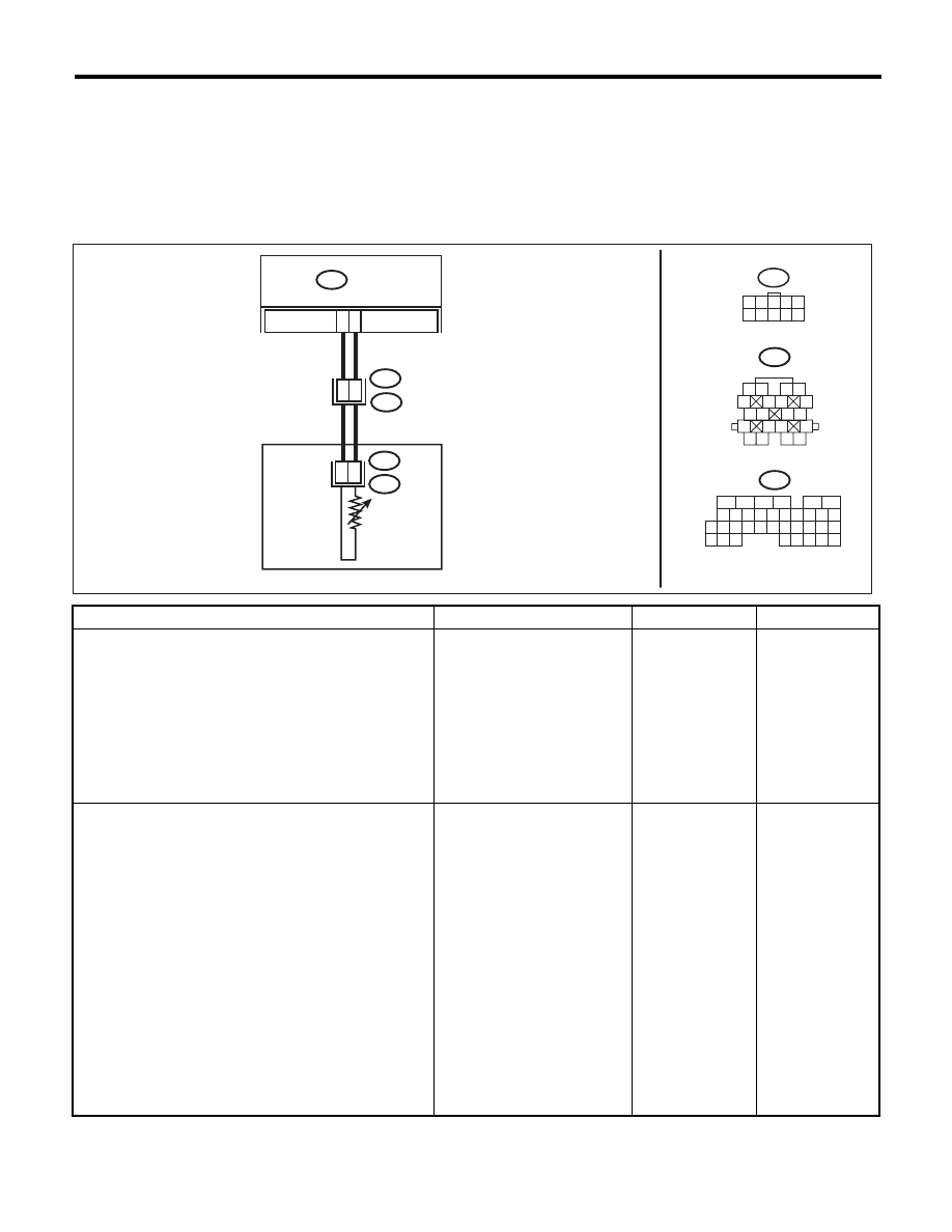
WIRING DIAGRAM:
Step
Check
Yes
No
1
CHECK HARNESS CONNECTOR BETWEEN
TCM AND TRANSMISSION.
1) Turn the ignition switch to OFF.
2) Disconnect the connectors from TCM and
transmission.
3) Measure the resistance of harness between
TCM and transmission connector.
Connector & terminal
(B54) No. 17 — (B11) No. 5:
(B54) No. 18 — (B11) No. 12:
Is the resistance less than 1
:? Go to step 2.
Repair the open
circuit of harness
between TCM and
transmission con-
nector.
2
CHECK ATF OIL TEMPERATURE SENSOR.
1) Turn the ignition switch to OFF.
2) Connect the connectors to transmission and
TCM.
3) Turn the ignition switch to ON and start
engine.
4) Warm up the transmission until the ATF
temperature exceeds 80°C (176°F).
NOTE:
If the ambient temperature is below 0°C (32°F),
drive the vehicle until the ATF reaches its oper-
ating temperature.
5) Disconnect the connector from transmis-
sion.
6) Measure the resistance between transmis-
sion connector terminals.
Connector & terminal
(T4) No. 5 — (T4) No. 12:
Is the resistance 300 — 800
:? Go to step 3.
Go to step 5.
TCM
B11
1
2
3 4
5
6 7
8
9
13
14 15
20
19
17
16
10
11 12
18
18
B54
B11
T10
T4
12
B54
5
6
7 8
2
1
9
4
3
10
24
22 23
25
11 12 13 14 15
26 27
28
16
17 18 19 20 21
33 34
29
32
30
31
35
CONTROL VALVE BODY
T10
1 2 3 4
6 7 8 9
5
10
17
5
4
3
T20
A
TF TEMPERA
TURE
SENSOR
AT-04348