Subaru Legacy IV (2008 year). Manual - part 750
5AT(diag)-15
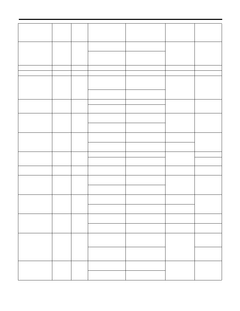
Transmission Control Module (TCM) I/O Signal
AUTOMATIC TRANSMISSION (DIAGNOSTICS)
H & LR/C solenoid
output
B54
5
While driving at 2nd of
manual mode
5 V or more
3 — 9
:
(ATF temperature
20°C (68°F))
Drive frequency:
300 Hz
While driving at 1st,
3rd-5th of manual
mode
Less than 1.5 V
Power GND
B54
13
Always
Approx. 0 V
—
Analog GND
B54
18
Always
Approx. 0 V
—
Fr/B solenoid output
B54
4
While driving at other
than 4th of manual
mode
5 V or more
3 — 9
:
(ATF temperature
20°C (68°F))
Drive frequency:
300 Hz
While driving at 4th of
manual mode
Less than 1.5 V
L/U solenoid output
B54
7
When lock-up
3 V or more
3 — 9
:
(ATF temperature
20°C (68°F))
Drive frequency:
300 Hz
When not lock-up
Less than 1 V
D/C solenoid output
B54
1
While driving at 1st or
5th of manual mode
5 V or more
3 — 9
:
(ATF temperature
20°C (68°F))
Drive frequency:
300 Hz
While driving at 2nd-4th
of manual mode
Less than 1.5 V
D/C oil pressure
switch input
B54
22
While driving at 1st or
5th of manual mode
6 V or more
While driving at 2nd-4th
of manual mode
Less than 1.5 V
Subaru Select
Monitor
communication line
B55
8
Ignition switch ON
8 V or more
—
Ignition switch OFF
Less than 1 V
Sensor GND
(analog)
B54
16
Always
Approx. 0 V
—
H&LR/C oil pressure
switch input
B54
14
While driving at 2nd of
manual mode
6 V or more
—
While driving at 3rd-5th
of manual mode
Less than 1.5 V
Fwd/B solenoid
output
B54
19
While driving at 1st or
2nd of manual mode
5 V or more
Drive frequency:
300 Hz
While driving at 3rd-5th
of manual mode
Less than 1.5 V
Fwd/B oil pressure
switch input
B54
21
While driving at 1st or
2nd of manual mode
Less than 1.5 V
While driving at 3rd-5th
of manual mode
6 V or more
Front vehicle speed
sensor input
B54
24
While driving at 2nd
and 20 km/h (12 MPH)
of manual mode
Approx. 500 — 700 rpm
—
Use the Subaru
Select Monitor.
While driving at 4th and
80 km/h (50 MPH) of
manual mode
Approx.
2,000 — 2,500 rpm
Use the Subaru
Select Monitor.
Inhibitor switch 1
input
B54
8
Ignition switch ON,
“P” range
Less than 0.5 V
—
Ignition switch ON,
“N” range
5 V or more
Item
Connector
No.
Terminal
No.
Measuring condition
Measured value
Resistance
between terminal
and chassis
ground
Remarks