Subaru Legacy IV (2008 year). Manual - part 703
4AT(diag)-33
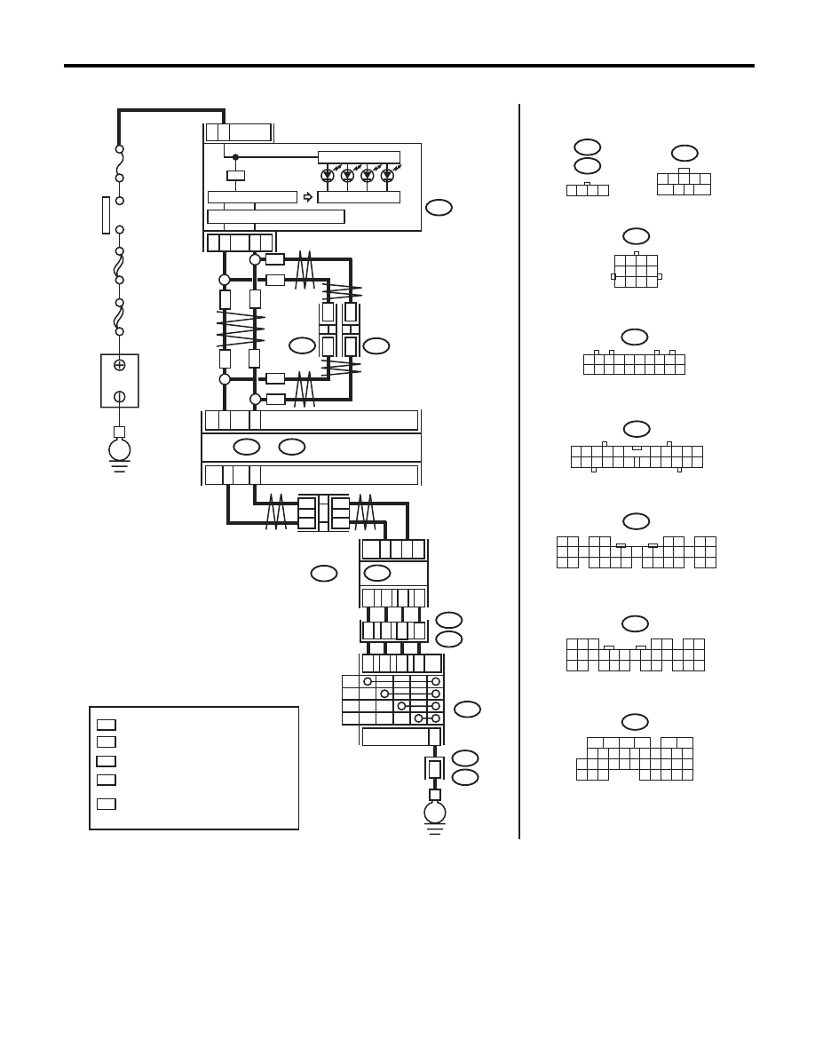
Diagnostic Procedure with Diagnostic Trouble Code (DTC)
AUTOMATIC TRANSMISSION (DIAGNOSTICS)
WIRING DIAGRAM:
AT-04898
MAIN SBF
SBF-6
No.
5
E
P
R
N
D
17
18
10
14
11
T7
B54
B12
T3
T3
B12
1
4
P
R
N
D
E
TCM
2
5
3
4
2
8
3
1
13
3
21
22
i10
i84
A:
B280
B:
A26
A27
B30
B20
B365
1
*
2
*
1
*
2
*
WN
WN
ON
i107
i106
*
*
*
*
ON
WN
WN
ON
ON
:
:
1
*
2
*
:
*
:
WN
:
ON
B54
B12
T7
9
8
7
6
5
4
3
2
1
10
9
12
11
8
7
6
5
4
3
2
1
5
6
7 8
2
1
9
4
3
10
24
22 23
25
11 12 13 14 15
26 27
28
16
17 18 19 20 21
33 34
29
32
30
31
35
i10
i84
B280
2
1
3 4
6 7 8 9 10
22
21
20
19
18
17
16
15
14
13
12
11
5
8
7
6
5
4
3
2
1
22 23
21
20
19
16
15
14
13
12
11
10
9
34 35
33
32
17
30
18
31
29
28
27
26
25
24
8
7
6
5
4
3
2
1
22
23
21
20
19
16
15
14
13
12
11
10
9
17
30
18
29
28
27
26
25
24
A:
B:
i107
i106
1 2 3 4 5 6 7 8 9 10
11 12 13 14 15 16 17 18 19 20
1 2 3 4
B365
WITH NAVIGATION
WITHOUT NAVIGATION
TERMINAL No. OPTIONAL ARRANGEMENT
AMONG 1, 2, 3, 11, 12 AND 13
TERMINAL No. OPTIONAL ARRANGEMENT
TERMINAL No. OPTIONAL ARRANGEMENT
AMONG 8, 9, 10, 18, 19 AND 20
CAN
JOINT
CONNECTOR
BODY INTEGRATED UNIT
COMBINATION
METER
IGNITION
SWITCH
CAN TRANSCEIVER & RECEIVER
MICRO COMPUTER
INHIBITOR
SWITCH
B
A
TTER
Y
CAN
JOINT
CONNECTOR
CAN
JOINT
CONNECTOR