Subaru Legacy IV (2008 year). Manual - part 698
4AT(diag)-13
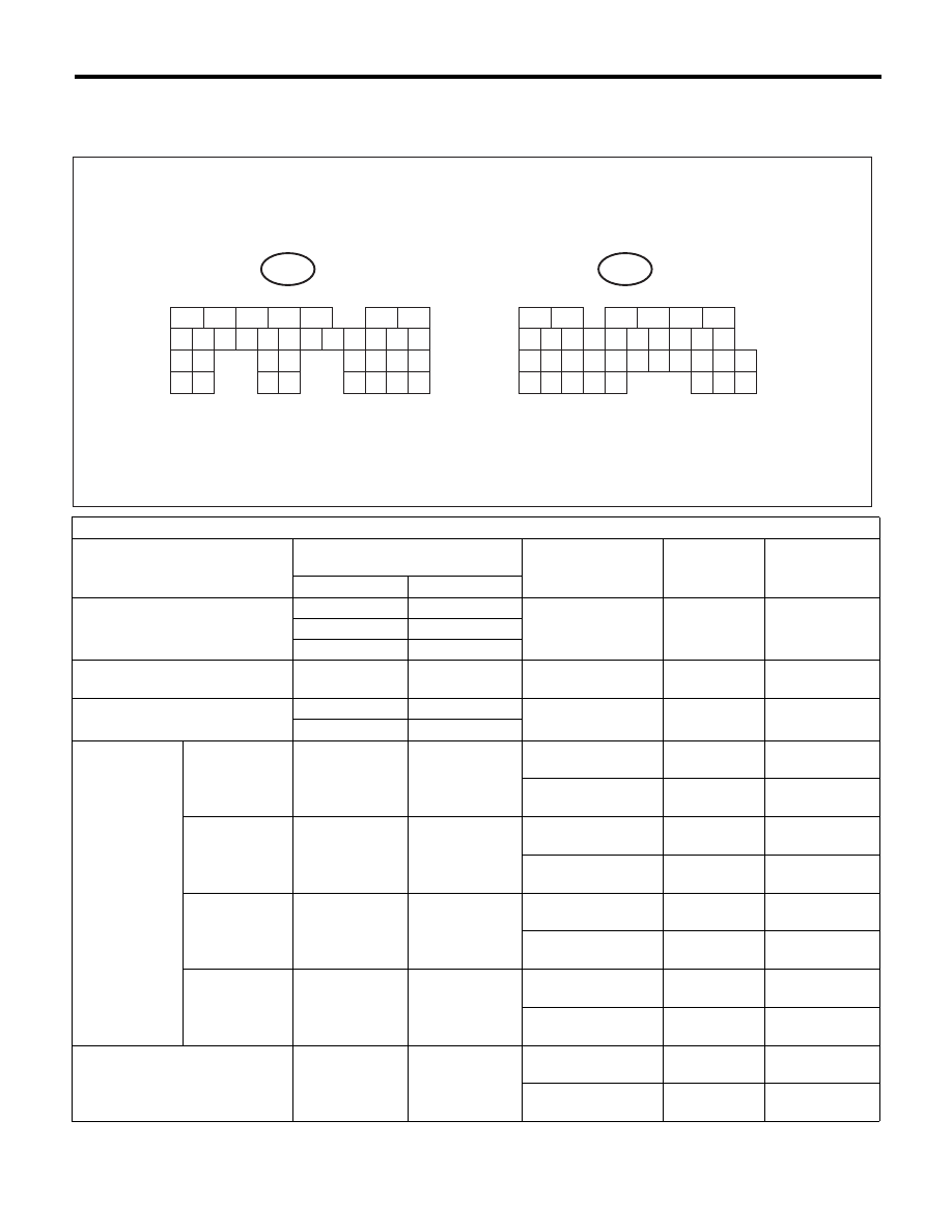
Transmission Control Module (TCM) I/O Signal
AUTOMATIC TRANSMISSION (DIAGNOSTICS)
5. Transmission Control Module (TCM) I/O Signal
A: ELECTRICAL SPECIFICATION
Check with ignition switch ON.
Contents
Measured terminal
(Connector & Terminal No.)
Measuring condition
Voltage (V)
Resistance (
:)
Positive terminal
Ground terminal
Backup power supply
(B55) No. 27
Chassis ground
—
10 — 13
—
(B55) No. 26
Chassis ground
(B55) No. 25
Chassis ground
ACC power supply
(B55) No. 12
Chassis ground
Ignition
Switch ACC
10 — 13
—
Ignition power supply
(B55) No. 1
Chassis ground
Ignition
Switch ON
10 — 13
—
(B55) No. 2
Chassis ground
Inhibitor switch
“P” range
switch
(B54) No. 14
Chassis ground
Select lever
“P” range
Less than 1
—
Select lever
Except “P” range
8 or more
—
“N” range
switch
(B54) No. 11
Chassis ground
Select lever
“N” range
Less than 1
—
Select lever
Except “N” range
8 or more
—
“R” range
switch
(B54) No. 13
Chassis ground
Select lever
“R” range
Less than 1
—
Select lever
Except “R” range
8 or more
—
“D” range
switch
(B54) No. 10
Chassis ground
Select lever
“D” range
Less than 1
—
Select lever
Except “D” range
8 or more
—
ATF temperature sensor
(B54) No. 23
(B54) No. 12
ATF temperature
20°C (68°F)
3.5 — 4.3
2.5k — 7.0 k
ATF temperature
80°C (176°F)
1.0 — 2.2
300 — 800
5
6
7
8
2
1
9
4
3
10
24
22
23
25
11
12
13
14
15
26
27
28
16
17
18
19
20
21
29
30
31
32
33
34
35
B55
TO
TO
5
6
7
8
2
1
9
4
3
10
24
22
23
25
11
12
13
14
15
26
27
28
16
17
18
19
20
21
33
34
29
32
30
31
35
B54
AT-03733