Subaru Legacy IV (2008 year). Manual - part 694


  Index      Subaru     Subaru Legacy IV - service repair manual 2008 year


Search            


Content   ..  692  693  694  695   ..


Subaru Legacy IV (2008 year). Manual - part 694


4AT-124

AT Main Case

AUTOMATIC TRANSMISSION

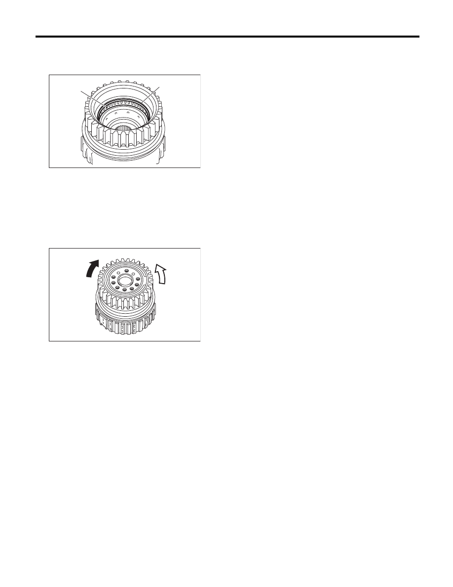
5. ONE-WAY CLUTCH OUTER RACE

1) Install the needle bearing, and then secure with
the snap ring.

2) Install the one-way clutch and one-way clutch in-
ner race, then secure with the snap ring.
3) Set the inner race. Make sure that the clutch
locks in the clockwise direction and rotates freely in
the counterclockwise direction.

E: INSPECTION

1. HIGH CLUTCH AND REVERSE CLUTCH

Check the following items.
• Drive plate facing for wear or damage
• Driven plate for discoloration (burned color)
• Snap ring wear and spring retainer deformation
• Wear and damage of the lip seal and D-ring
• Piston and piston check ball operation
• Adjust the total end play. <Ref. to 4AT-88, AD-
JUSTMENT, Oil Pump Housing.>

2. PLANETARY GEAR AND LOW CLUTCH

Check the following items.
• Drive plate facing for wear or damage
• Driven plate for discoloration (burned color)
• Snap ring wear and spring retainer deformation
• Wear and damage of the lip seal and D-ring
• Measure the total end play and adjust it to be
within specifications. <Ref. to 4AT-88, ADJUST-
MENT, Oil Pump Housing.>

3. 2-4 BRAKE

Check the following items.
• Drive plate facing for wear or damage
• Driven plate for discoloration (burned color)
• Snap ring wear, leaf spring setting and break-
age, and spring retainer deformation
• Wear and damage of the lip seal and D-ring
• Measure the total end play and adjust it to be
within specifications. <Ref. to 4AT-88, ADJUST-
MENT, Oil Pump Housing.>

4. ONE-WAY CLUTCH

• Check that the snap ring is not damaged and the
seal ring is not deformed.
• Measure the total end play and adjust it to be
within specifications. <Ref. to 4AT-88, ADJUST-
MENT, Oil Pump Housing.>

5. LOW & REVERSE BRAKE

Check the following items.
• Drive plate facing for wear or damage
• Driven plate for discoloration (burned color)
• Snap ring wear, leaf spring setting and break-
age, and spring retainer deformation
• Lip seal wear and damage

(A) Needle bearing

(B) Snap ring

(A) Lock

(B) Free

AT-00268

(B)

(A)

AT-00282

(B)

(A)

4AT-125

Transmission Control Device

AUTOMATIC TRANSMISSION

35.Transmission Control Device

A: REMOVAL

1) Remove the transmission assembly from vehicle
body. <Ref. to 4AT-35, REMOVAL, Automatic
Transmission Assembly.>
2) Pull out the torque converter clutch assembly.
<Ref. to 4AT-67, REMOVAL, Torque Converter
Clutch Assembly.>
3) Remove the input shaft.
4) Lift up the lever on the rear side of transmission
harness connector, and then remove it from the
stay.
5) Disconnect the air breather hose. <Ref. to 4AT-
65, REMOVAL, Air Breather Hose.>
6) Remove the inhibitor switch connector from the
stay.
7) Wrap vinyl tape around the nipple attached to
the air breather hose.
8) Remove the pitching stopper bracket.
9) Remove the inhibitor switch. <Ref. to 4AT-47,
REMOVAL, Inhibitor Switch.>
10) Remove the control valve body assembly.
<Ref. to 4AT-56, REMOVAL, Control Valve Body.>
11) Pull out the straight pin of manual plate.

12) Remove the bolts securing select lever, and
then remove the select lever, manual plate and
parking rod.

NOTE:
Be careful not to damage the lips of press-fitted oil
seal in the case.

13) Remove the detent spring.

AT-04847

(A) Bolt

(B) Range select lever

(C) Manual plate

(D) Parking rod

AT-04845

(B)

(C)

(D)

(A)

AT-04846

4AT-126

Transmission Control Device

AUTOMATIC TRANSMISSION

B: INSTALLATION

1) Install the detent spring to the transmission
case.

Tightening torque:

6 N·m (0.6 kgf-m, 4.4 ft-lb)

2) Insert the range select lever, and tighten the
bolts.

Tightening torque:

6 N·m (0.6 kgf-m, 4.4 ft-lb)

3) Insert the manual plate and parking rod.

4) Insert a new straight pin to manual plate.

5) Install the oil pan and the control valve assem-
bly. <Ref. to 4AT-57, INSTALLATION, Control
Valve Body.>
6) Turn over the transmission case to its original
position.
7) Install the pitching stopper bracket.

Tightening torque:

41 N·m (4.2 kgf-m, 30.2 ft-lb)

8) Install and adjust the inhibitor switch. <Ref. to
4AT-46, Inhibitor Switch.>
9) Insert the inhibitor switch connector and trans-
mission harness connector onto the stay.

10) Install the air breather hose. <Ref. to 4AT-65,
INSTALLATION, Air Breather Hose.>

(A) Bolt

(B) Range select lever

(C) Manual plate

(D) Parking rod

AT-04846

AT-04849

AT-04845

(B)

(C)

(D)

(A)

(A) Transmission harness connectors

(B) Inhibitor switch connector

AT-04847

AT-01351

(B)

(A)

4AT-127

Transmission Control Device

AUTOMATIC TRANSMISSION

11) Insert the input shaft while rotating it lightly by
hand, and then check the amount of protrusion.

Normal protrusion A:

50 — 55 mm (1.97 — 2.17 in)

12) Install the torque converter clutch assembly.
<Ref. to 4AT-67, INSTALLATION, Torque Convert-
er Clutch Assembly.>
13) Install the transmission assembly to the vehi-
cle. <Ref. to 4AT-38, INSTALLATION, Automatic
Transmission Assembly.>

C: INSPECTION

Make sure that the manual lever and detent spring
are not worn or otherwise damaged.

A Measured value

AT-03204

A


Content   ..  692  693  694  695   ..