Subaru Legacy IV (2008 year). Manual - part 676
4AT-52
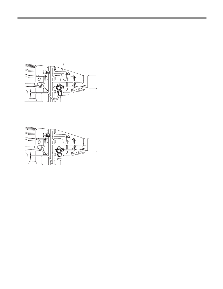
Rear Vehicle Speed Sensor
AUTOMATIC TRANSMISSION
15.Rear Vehicle Speed Sensor
A: REMOVAL
1) Set the vehicle on a lift.
2) Disconnect the ground cable from battery.
3) Lift up the vehicle.
4) Disconnect the connector from the rear vehicle
speed sensor.
5) Remove the rear vehicle speed sensor.
B: INSTALLATION
Install in the reverse order of removal.
NOTE:
Replace the O-ring with a new part.
Tightening torque:
7 N·m (0.7 kgf-m, 5.2 ft-lb)
(A) Rear vehicle speed sensor
AT-02207
(A)
AT-01341