Subaru Legacy IV (2008 year). Manual - part 672


  Index      Subaru     Subaru Legacy IV - service repair manual 2008 year


Search            


Content   ..  670  671  672  673   ..


Subaru Legacy IV (2008 year). Manual - part 672


4AT-36

Automatic Transmission Assembly

AUTOMATIC TRANSMISSION

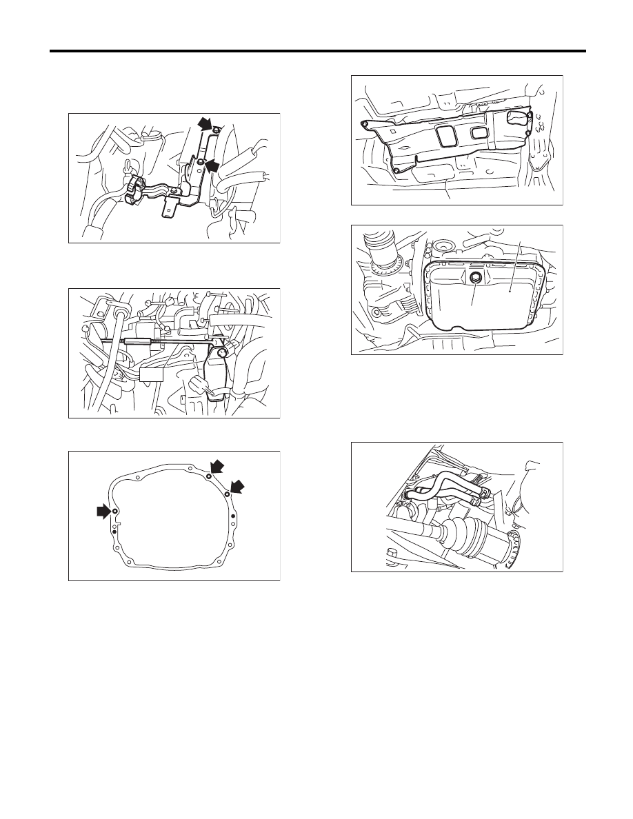
13) Disconnect the engine harness, then remove
the harness connector from the engine harness
bracket.
14) Remove the engine harness bracket.

15) Remove the pitching stopper bracket.
16) Set the ST.
ST

41099AC000 ENGINE SUPPORT ASSY

17) Remove the bolts which hold upper side of
transmission to engine.

18) Lift up the vehicle.
19) Remove the under cover.
20) Remove the front, center and rear exhaust
pipes and the muffler. <Ref. to EX(H4SO)-4, RE-
MOVAL, Front Exhaust Pipe.> <Ref. to EX(H4SO)-
7, REMOVAL, Center Exhaust Pipe.> <Ref. to
EX(H4SO)-8, REMOVAL, Rear Exhaust Pipe.>
<Ref. to EX(H4SO)-10, REMOVAL, Muffler.>

21) Remove the heat shield cover.

22) Remove the drain plug (ATF) to drain the ATF.

23) Disconnect the ATF cooler hoses from the
pipes of the transmission side, and remove the oil
charge pipe.

24) Remove the propeller shaft. <Ref. to DS-10,
REMOVAL, Propeller Shaft.>
25) Remove the shift select cable. <Ref. to CS-28,
REMOVAL, Select Cable.>
26) Remove the brackets (two) which hold front
stabilizer.

AT-04581

AT-02167

ST

AT-00106

(A) Oil pan

(B) Drain plug (ATF)

AT-01331

AT-04829

(B)

(A)

AT-04831

4AT-37

Automatic Transmission Assembly

AUTOMATIC TRANSMISSION

27) Remove the bolt securing the ball joint of the
front arm to housing.

28) Pull out the front drive shaft from the transmis-
sion.

(1) Using a tire lever or a crow bar, etc., pull out
until the front drive shaft transmission side joint
slides move smoothly.

NOTE:
Place cloth between the tire lever or bar and the
transmission in order to avoid damaging the trans-
mission side retainer.

(2) Hold the transmission side joint of the front
drive shaft by hand and extract the housing
from the transmission while pressing the hous-
ing outward, so as not to stretch the boot.

29) Remove the bolts which hold the clutch hous-
ing cover.
30) Remove the bolts and nuts which hold lower
side of transmission to engine.

31) Place the transmission jack under the transmis-
sion.

NOTE:
Make sure that the support plates of transmission
jack do not touch the oil pan.

32) Remove the transmission rear crossmember
from the vehicle.

33) While lowering the transmission jack gradually,
fully retract the engine support, and then tilt the en-
gine rearward.

NOTE:
Retract the support until the clearance between
front crossmember and converter case becomes
approx. 10 mm (0.39 in).
34) Remove the transmission.

NOTE:
Remove the transmission and torque converter as
a single unit from engine.

35) Remove the rear cushion rubber from the
transmission assembly.

AT-00809

AT-00108

AT-03697

AT-04857

4AT-38

Automatic Transmission Assembly

AUTOMATIC TRANSMISSION

B: INSTALLATION

1) Replace the differential side oil seal with a new
part. <Ref. to 4AT-45, REPLACEMENT, Differen-
tial Side Retainer Oil Seal.>

NOTE:
When a new oil seal has been installed, replace-
ment is not required.
2) Install the rear cushion rubber to the transmis-
sion assembly.

Tightening torque:

40 N·m (4.1 kgf-m, 29.5 ft-lb)

3) Attach the ST to the converter case.
ST

498277200

STOPPER SET

4) Install the transmission onto the engine.

(1) Lift up the transmission gradually using
transmission jack.

(2) Insert the engine side stud bolt into the
transmission bolt hole.
(3) While raising the transmission jack gradual-
ly, turn the screw of engine support, then tilt the
engine forward and connect.

5) Install the transmission rear crossmember.

Tightening torque:

T1: 35 N·m (3.6 kgf-m, 25.8 ft-lb)
T2: 75 N·m (7.6 kgf-m, 55.3 ft-lb)

6) Remove the transmission jack.
7) Tighten the bolts and nuts which hold the lower
side of transmission to the engine.

Tightening torque:

50 N·m (5.1 kgf-m, 36.9 ft-lb)

8) Install the clutch housing cover bolts.
9) Lower the vehicle.
10) Connect the engine and transmission.

(1) Remove the ST from converter case.

NOTE:
When removing the ST, be careful not to drop it into
converter case.

(2) Install the starter. <Ref. to SC(H4SO)-6, IN-
STALLATION, Starter.>
(3) Tighten the bolts which hold the upper side
of the transmission to the engine.

Tightening torque:

50 N·m (5.1 kgf-m, 36.9 ft-lb)

AT-00103

ST

AT-04857

T 2

T 2

T 1

AT-03698

AT-00108

AT-00106

4AT-39

Automatic Transmission Assembly

AUTOMATIC TRANSMISSION

11) Install the torque converter clutch assembly to
the drive plate.

CAUTION:
• Be careful not to damage the mounting bolts.
• Be careful not to drop bolts into the converter
case.

(1) Tighten the bolts which hold the torque con-
verter clutch assembly to the drive plate.
(2) Place the wrench on the crank pulley bolt,
and remove all the bolts while rotating the crank
pulley a little bit at a time.

Tightening torque:

25 N·m (2.5 kgf-m, 18.4 ft-lb)

(3) Fit the plug to service hole.
(4) Install the V-belt cover.

12) Remove the ST.

13) Install the engine harness bracket.

Tightening torque:

16 N·m (1.6 kgf-m, 11.8 ft-lb)

14) Install the harness connector to engine harness
bracket, then connect the harness.

15) Install the pitching stopper bracket.

Tightening torque:

41 N·m (4.2 kgf-m, 30.2 ft-lb)

16) Install the throttle body. <Ref. to FU(H4SO)-12,
INSTALLATION, Throttle Body.>
17) Install the pitching stopper.

Tightening torque:

T1: 50 N·m (5.1 kgf-m, 36.9 ft-lb)
T2: 58 N·m (5.9 kgf-m, 42.8 ft-lb)

18) Lift up the vehicle.
19) Replace the circlip of the front drive shaft with a
new part.
20) Apply grease to the oil seal lip.
21) Attach the ST to side retainer.
ST

28399SA010

OIL SEAL PROTECTOR

22) Align and insert the spline of the front drive
shaft to the splines of the differential bevel gear,
and remove the ST.

AT-00102

AT-02167

ST

AT-04581

(A) Pitching stopper bracket

AT-04642

(A)

T2

T1

AT-03878

AT-00110

ST


Content   ..  670  671  672  673   ..