Subaru Legacy IV (2008 year). Manual - part 594


  Index      Subaru     Subaru Legacy IV - service repair manual 2008 year


Search            


Content   ..  592  593  594  595   ..


Subaru Legacy IV (2008 year). Manual - part 594


EN(H6DO)(diag)-349

Diagnostic Procedure without Diagnostic Trouble Code (DTC)

ENGINE (DIAGNOSTICS)

1. EVEN WHEN THE SI-DRIVE MODE IS CHANGED, THE MULTI-INFORMATION DISPLAY 
DOES NOT CHANGE, AND THE MODE DOES NOT SWITCH.
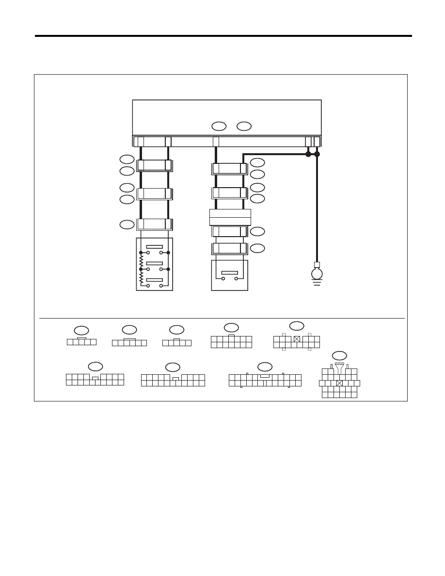
WIRING DIAGRAM:

EN-05720

i1

5 6 7 8

2

1

9

4

3

10

24

22

23

25

27

26

28

11 12 13

14 15 16

17 18 19 20 21

C7

1 2 3 4 5

B68

1 2 3 4 5 6 7
8 9 10 11 12 13 14

1 2 3

4 5 6

7 8 9 10 11 12 13 14

B:

i11

A:

i10

3 4 5

6 7 8 9

19 20 21

14 15 16

17 18

1 2

10

12

11

13

22

i54

1
9

2 3

8

10

4

11 12 13 14 15 16

5 6 7

17 18

R43

2 3 4 5

6 7 8 9

11 12 13 14

17 18 19 20

1

10

15 16

ST4

2 3 4 5

1

6

i10

A:

i11

B:

A11

A12

B9

B12

i1

B36

9

24

i54

R99

2

1

R43

C1

15

16

B8

3

2

ST1

ST4

B68

12

5

4

3

C7

I

S#

S

E

4

5

ST5

ST5

2 3 4 5

1

COMBINATION 

METER

ROLL 
CONNECTOR

SI-DRIVE

SELECTOR

SI-DRIVE S# 

SWITCH

EN(H6DO)(diag)-350

Diagnostic Procedure without Diagnostic Trouble Code (DTC)

ENGINE (DIAGNOSTICS)

Step

Check

Yes

No

1

CHECK SI-DRIVE SELECTOR.
1) Disconnect the connector from the multi-
information display meter.
2) Measure the resistance between connec-
tors when the SI-DRIVE selector is operated.

Connector & terminal

(i11) No. 9 — (i11) No. 12:

Does the resistance change as 
shown below?
S#: 2.14 — 3.2 k

:

I: 0.8 — 1.2 k

:

S: Less than 10 

:

Go to step 2.

Go to step 5.

2

CHECK SI-DRIVE S# SWITCH.
1) Hold down the SI- DRIVE S# switch.
2) Measure the resistance of harness between 
the multi-information display meter connector 
and chassis ground.

Connector & terminal

(i11) No. 8 — Chassis ground:

Is the resistance less than 10 

:? Go to step 3.

Go to step 6.

3

CHECK POOR CONTACT.
Check the following items.
• Cracked or improperly connected connector
• Broken connector pin
• Disconnection connector terminal

Is there any abnormal condi-
tion?

Correct the cause 
of trouble.

Go to step 4.

4

RECHECK FAULT.
1) Connect all connectors.
2) Change the SI-DRIVE mode.

Is there any abnormal condi-
tion?

Replace the multi-
information dis-
play meter. <Ref. 
to IDI-22, Combi-
nation Meter.>

The circuit has 
returned to a nor-
mal condition at this 
time. Reproduce 
the failure, and then 
perform the diagno-
sis again.

NOTE:
In this case, tem-
porary poor con-
tact of connector
may be the cause.

5

CHECK SI-DRIVE SELECTOR HARNESS 
AND CONNECTOR.
Check the following items.
• Short or open circuit in the harness
• Improperly connected or loose terminal in the 
SI-DRIVE selector connector
• Improperly connected or loose terminal in 
coupling connector

Is there any abnormal condi-
tion?

Correct the cause 
of trouble.

Go to step 7.

6

CHECK SI-DRIVE S# SWITCH HARNESS 
AND CONNECTOR.
Check the following items.
• Short or open circuit in the harness
• Improperly connected or loose terminal in 
steering roll connector
• Improperly connected or loose terminal in 
coupling connector

Is there any abnormal condi-
tion?

Correct the cause 
of trouble.

Go to step 7.

7

RECHECK FAULT.
1) Connect all connectors.
2) Change the SI-DRIVE mode.

Is there any abnormal condi-
tion?

Replace the SI-
DRIVE selector or 
SI-DRIVE S# 
switch. <Ref. to 
FU(H6DO)-36, SI-
DRIVE (SUBARU 
Intelligent Drive) 
Selector.> or <Ref. 
to FU(H6DO)-37, 
SI-DRIVE (SUB-
ARU Intelligent 
Drive) S# Switch.>

The circuit has 
returned to a nor-
mal condition at this 
time. Reproduce 
the failure, and then 
perform the diagno-
sis again.

NOTE:
In this case, tem-
porary poor con-
tact of connector
may be the cause.

EN(H6DO)(diag)-351

Diagnostic Procedure without Diagnostic Trouble Code (DTC)

ENGINE (DIAGNOSTICS)

2. WHEN THE SI-DRIVE MODE IS CHANGED, “MODE CHANGE ERROR” APPEARS IN THE 
MULTI INFORMATION DISPLAY APPROXIMATELY 5 SECONDS LATER.

Step

Check

Yes

No

1

CHECK DTC.

Is DTC displayed?

Check the corre-
sponding DTC 
using the “List of 
Diagnostic Trouble 
Code (DTC)” for 
each unit.

Go to step 2.

2

CHECK DISPLAY OF MULTI-INFORMATION 
DISPLAY METER.
Check whether there are other errors displayed 
other than the “Mode Change Error”.
Examples:
• “Err” is displayed in the external temperature 
or fuel consumption displays.
• FUEL gauge, TEMP gauge or ECO gauge 
does not move.

Is there other errors displayed 
other than the “Mode Change 
Error”?

For the diagnostic 
procedure, refer to 
LAN section. <Ref. 
to LAN(diag)-2, 
Basic Diagnostic 
Procedure.>

Go to step 3.

3

CHECK MULTI-INFORMATION DISPLAY 
METER AND ECM.

Is the multi-information display 
meter and ECM part numbers 
correct?

Replace the multi-
information dis-
play meter. <Ref. 
to IDI-22, Combi-
nation Meter.>

Replace the multi-
information dis-
play meter or ECM 
to that of the cor-
rect part number. 
<Ref. to IDI-22, 
Combination 
Meter.> or <Ref. to 
FU(H6DO)-38, 
Engine Control 
Module (ECM).>

EN(H6DO)(diag)-352

Diagnostic Procedure without Diagnostic Trouble Code (DTC)

ENGINE (DIAGNOSTICS)

3. WHEN THE SI-DRIVE MODE IS CHANGED, “MODE CHANGE ERROR” IS NOT DISPLAYED 
IN MULTI-INFORMATION DISPLAY, AND “S#”, “I”, “S” FLASHES.

NOTE:
In this case, there may be a problem outside the SI-DRIVE system.

Step

Check

Yes

No

1

CHECK MALFUNCTION INDICATOR LIGHT.
1) Start the engine.
2) Check whether the malfunction indicator 
light is lit or not.

Does the malfunction indicator 
light illuminate?

Check the appro-
priate DTC using 
the “List of Diag-
nostic Trouble 
Code (DTC)”. 
<Ref. to 
EN(H6DO)(diag)-
81, List of Diagnos-
tic Trouble Code 
(DTC).>

Go to step 2.

2

CHECK ENGINE COOLANT TEMPERATURE 
GAUGE.
1) Turn the ignition switch to ON.
2) Check the engine coolant temperature 
gauge.

Is it overheating?

Investigate and 
repair the cause of 
overheating.

Go to step 3.

3

CHECK ENGINE OIL TEMPERATURE.
1) Turn the ignition switch to ON.
2) Check the engine oil temperature using 
Subaru Select Monitor.

NOTE:
For detailed operation procedure, refer to
“READ CURRENT DATA FOR ENGINE”. <Ref.
to EN(H6DO)(diag)-34, Subaru Select Moni-
tor.>

Is the engine oil temperature 
117°C (243°F) or higher?

Inspect and repair 
the cause of 
engine oil tempera-
ture rise.

NOTE:
Ask the customer
whether the vehi-
cle has experi-
enced a long drive
in low gear or tow-
ing of heavy load. If
not, drive the vehi-
cle again after the
engine oil temper-
ature lowers, and
check if the oil tem-
perature rises.

Go to step 4.

4

CHECK DISPLAY OF MULTI-INFORMATION 
DISPLAY.
1) Turn the ignition switch to ON.
2) Change the SI-DRIVE mode.
3) Check the display of the multi-information 
display.

Do the displays “S#”, “I”, “S” of 
the multi-information display 
flash?

Replace the multi-
information dis-
play meter. <Ref. 
to IDI-22, Combi-
nation Meter.>

Perform test opera-
tion, and check the 
malfunction indica-
tor, the engine 
coolant tempera-
ture gauge and the 
engine oil tempera-
ture. If they are 
operating normally, 
end the diagnosis.


Content   ..  592  593  594  595   ..