Subaru Legacy IV (2008 year). Manual - part 568
EN(H6DO)(diag)-245
Diagnostic Procedure with Diagnostic Trouble Code (DTC)
ENGINE (DIAGNOSTICS)
CG:DTC P0451 EVAPORATIVE EMISSION CONTROL SYSTEM PRESSURE
SENSOR
DTC DETECTING CONDITION:
• Two consecutive driving cycles with fault
• GENERAL DESCRIPTION <Ref. to GD(H6DO)-128, DTC P0451 EVAPORATIVE EMISSION CONTROL
SYSTEM PRESSURE SENSOR, Diagnostic Trouble Code (DTC) Detecting Criteria.>
CAUTION:
After repair or replacement of faulty parts, perform Clear Memory Mode <Ref. to EN(H6DO)(diag)-52,
OPERATION, Clear Memory Mode.>, and Inspection Mode <Ref. to EN(H6DO)(diag)-44, PROCEDURE,
Inspection Mode.>.
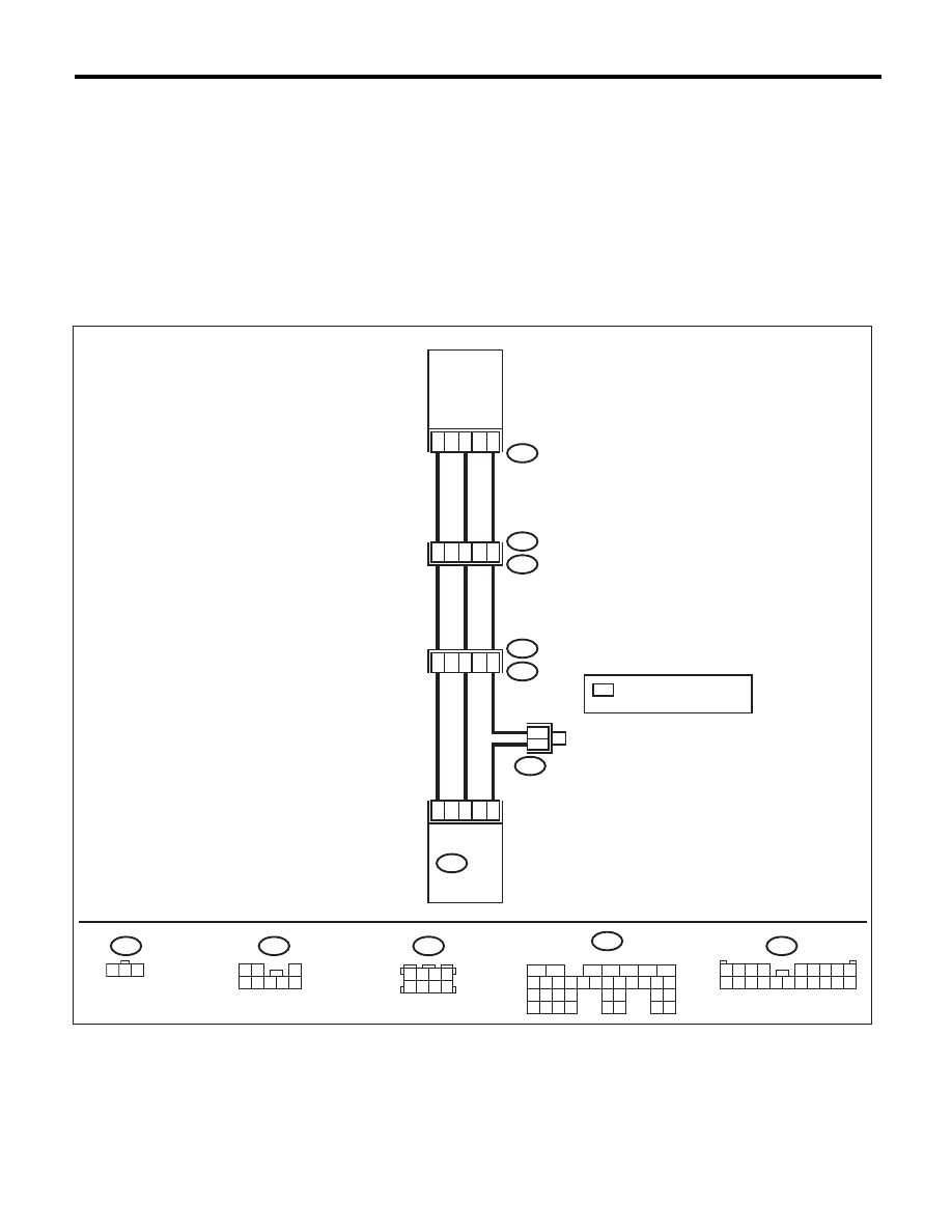
WIRING DIAGRAM:
B83
3
1
2
22
32
30
ECM
B135
R47
R213
R15
R1
B97
B97
1 2 3
R47
B135
7
4
6
6
13
17
B83
R213
FUEL
TANK
PRESSURE
SENSOR
1 2 3 4
5 6 7 8 9
10 11 12 13 14 15 16 17 18 19 20
3 4
5 6
1 2
7 8
1 2
3
4 5 6 7 8
:TERMINAL No. OPTIONAL
ARRANGEMENT
*
*
*
5
6
7
8
2
1
9
4
3
10
24
22 23
25
11 12 13 14 15
26 27
28
16 17 18 19
20 21
29 30 31
32 33
34 35
EN-05233