Subaru Legacy IV (2008 year). Manual - part 540
EN(H6DO)(diag)-133
Diagnostic Procedure with Diagnostic Trouble Code (DTC)
ENGINE (DIAGNOSTICS)
Y: DTC P0107 MANIFOLD ABSOLUTE PRESSURE/BAROMETRIC PRESSURE
CIRCUIT LOW INPUT
DTC DETECTING CONDITION:
• Immediately at fault recognition
• GENERAL DESCRIPTION <Ref. to GD(H6DO)-35, DTC P0107 MANIFOLD ABSOLUTE PRESSURE/
BAROMETRIC PRESSURE CIRCUIT LOW INPUT, Diagnostic Trouble Code (DTC) Detecting Criteria.>
CAUTION:
After repair or replacement of faulty parts, perform Clear Memory Mode <Ref. to EN(H6DO)(diag)-52,
OPERATION, Clear Memory Mode.>, and Inspection Mode <Ref. to EN(H6DO)(diag)-44, PROCEDURE,
Inspection Mode.>.
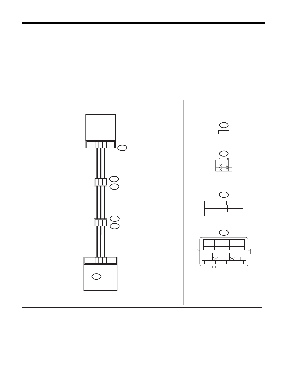
WIRING DIAGRAM:
5
6
7
8
2
1
9
4
3
10
24
22 23
25
11 12 13 14 15
26 27
28
16 17
18 19 20 21
33 34
29
32
30 31
1 2 3
MANIFOLD
ABSOLUTE
PRESSURE
SENSOR
1
3
2
5
8
1
29
6
19
19
20
7
ECM
B134
E21
E77
B21
E2
E76
B134
E21
E77
1 2
3 4
5
6
7
8
9
10
EN-06869
B21
1 2 3 4 5 6 7 8 9 10 11
12 13 14 15 16 17 18 19 20 21 22
23 24 25 26 27 28 29 30 31 32 33
34
35
42
43
36
37
38
39
48
49
50
51
52
53
54
40
41
44
45
46
47