Subaru Legacy IV (2008 year). Manual - part 460
FU(H6DO)-59
Fuel Sub Level Sensor
FUEL INJECTION (FUEL SYSTEMS)
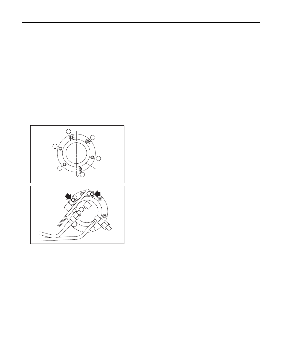
B: INSTALLATION
Install in the reverse order of removal while being
careful of the following.
• Make sure the sealing portion is free from fuel or
foreign matter before installation.
• Align protrusion (A) of the gasket to the position
shown in the following figure.
• Align the protrusion (B) of fuel sub level sensor
with the cutout on the upper plate of fuel sub level
sensor.
• Tighten the nuts and bolts to the specified torque
in the order as shown in the figure.
NOTE:
Use a new gasket and retainer.
Tightening torque:
4.4 N·m (0.4 kgf-m, 3.2 ft-lb)
1
6
5
2
4
3
(B)
(A)
FU-02836
FU-02674