Subaru Legacy IV (2008 year). Manual - part 364
EN(H4DOTC)(diag)-277
Diagnostic Procedure with Diagnostic Trouble Code (DTC)
ENGINE (DIAGNOSTICS)
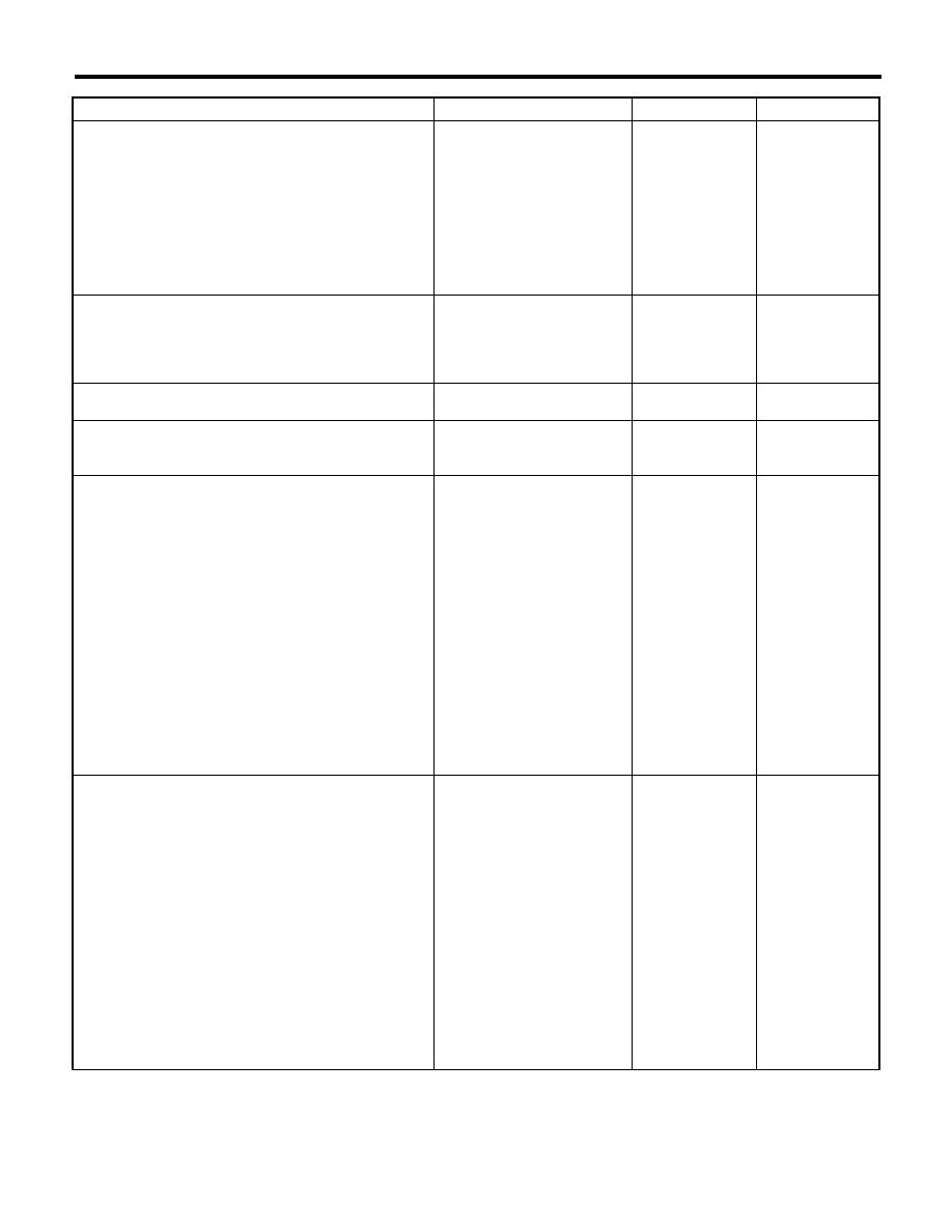
Step
Check
Yes
No
1
CHECK FOR ANY OTHER DTC ON DISPLAY. Is any other DTC displayed?
Check the appro-
priate DTC using
the “List of Diag-
nostic Trouble
Code (DTC)”.
<Ref. to
EN(H4DOTC)(diag)
-81, List of Diag-
nostic Trouble
Code (DTC).>
Go to step 2.
2
CHECK ENGINE OIL.
Is there a proper amount of
engine oil?
Go to step 3.
Replace engine oil.
<Ref. to
LU(H4SO)-10,
REPLACEMENT,
Engine Oil.>
3
CHECK EXHAUST SYSTEM.
Are there holes or loose bolts
on exhaust system?
Repair the exhaust
system.
Go to step 4.
4
CHECK AIR INTAKE SYSTEM.
Are there holes, loose bolts or
disconnection of hose on air
intake system?
Repair the air
intake system.
Go to step 5.
5
CHECK FUEL PRESSURE.
WARNING:
Place “NO OPEN FLAMES” signs near the
working area.
CAUTION:
Be careful not to spill fuel.
Measure the fuel pressure while disconnecting
pressure regulator vacuum hose from intake
manifold. <Ref. to ME(H4DOTC)-25, INSPEC-
TION, Fuel Pressure.>
CAUTION:
Release fuel pressure before removing the
fuel pressure gauge.
NOTE:
If fuel pressure does not increase, squeeze the
fuel return hose 2 to 3 times, then measure fuel
pressure again.
Is the measured value 284 —
314 kPa (2.9 — 3.2 kg/cm
2
,
41 — 46 psi)?
Go to step 6.
Repair the follow-
ing item.
Fuel pressure is
too high:
• Clogged fuel
return line or bent
hose
Fuel pressure is
too low:
• Improper fuel
pump discharge
• Clogged fuel
supply line
6
CHECK FUEL PRESSURE.
After connecting the pressure regulator vacuum
hose, measure fuel pressure. <Ref. to
ME(H4DOTC)-25, INSPECTION, Fuel Pres-
sure.>
CAUTION:
Release fuel pressure before removing the
fuel pressure gauge.
NOTE:
• If fuel pressure does not increase, squeeze
fuel return hose 2 to 3 times, then measure fuel
pressure again.
• If the measured value at this step is out of
specification, check or replace pressure regula-
tor and pressure regulator vacuum hose.
Is the measured value 230 —
260 kPa (2.35 — 2.65 kg/cm
2
,
33 — 38 psi)?
Go to step 7.
Repair the follow-
ing item.
Fuel pressure is
too high:
• Faulty pressure
regulator
• Clogged fuel
return line or bent
hose
Fuel pressure is
too low:
• Faulty pressure
regulator
• Improper fuel
pump discharge
• Clogged fuel
supply line