Subaru Legacy IV (2008 year). Manual - part 324
EN(H4DOTC)(diag)-117
Diagnostic Procedure with Diagnostic Trouble Code (DTC)
ENGINE (DIAGNOSTICS)
Q: DTC P0112 INTAKE AIR TEMPERATURE SENSOR 1 CIRCUIT LOW
DTC DETECTING CONDITION:
• Immediately at fault recognition
• GENERAL DESCRIPTION <Ref. to GD(H4DOTC)-34, DTC P0112 INTAKE AIR TEMPERATURE SEN-
SOR 1 CIRCUIT LOW, Diagnostic Trouble Code (DTC) Detecting Criteria.>
TROUBLE SYMPTOM:
• Improper idling
• Poor driving performance
CAUTION:
After repair or replacement of faulty parts, perform Clear Memory Mode <Ref. to EN(H4DOTC)(diag)-
52, OPERATION, Clear Memory Mode.>, and Inspection Mode <Ref. to EN(H4DOTC)(diag)-43, PRO-
CEDURE, Inspection Mode.>.
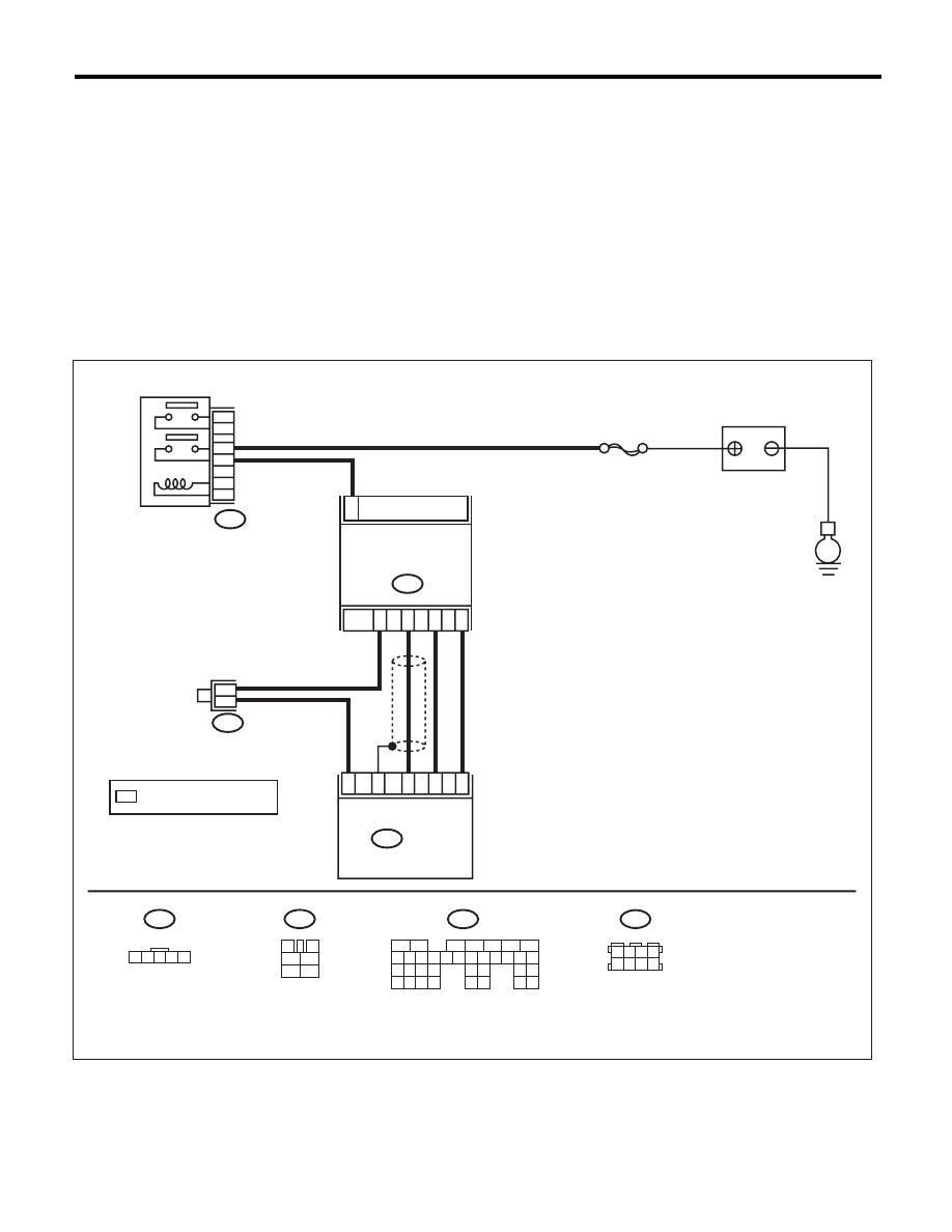
WIRING DIAGRAM:
EN-05087
B135
5
6
7
8
2
1
9
4
3
10
24
22 23
25
11 12 13 14 15
26 27
28
16 17 18 19
20 21
29 30 31
32 33
34 35
B3
E
B83
1
B3
ECM
B135
SBF-7
1 2 3 4 5
3
4
1
2
5
6
B47
*
*
2
4
3
5
34
18
26
30
35
B47
1
2
4
6
3
5
1 2 3 4
5 6 7 8
B83
BATTERY
MASS AIR FLOW &
INTAKE AIR
TEMPERATURE
SENSOR
MAIN RELAY
: TERMINAL No. OPTIONAL
ARRANGEMENT
*