Subaru Legacy IV (2008 year). Manual - part 285


  Index      Subaru     Subaru Legacy IV - service repair manual 2008 year


Search            


Content   ..  283  284  285  286   ..


Subaru Legacy IV (2008 year). Manual - part 285


CO(H4DOTC)-2

General Description

COOLING

1. General Description
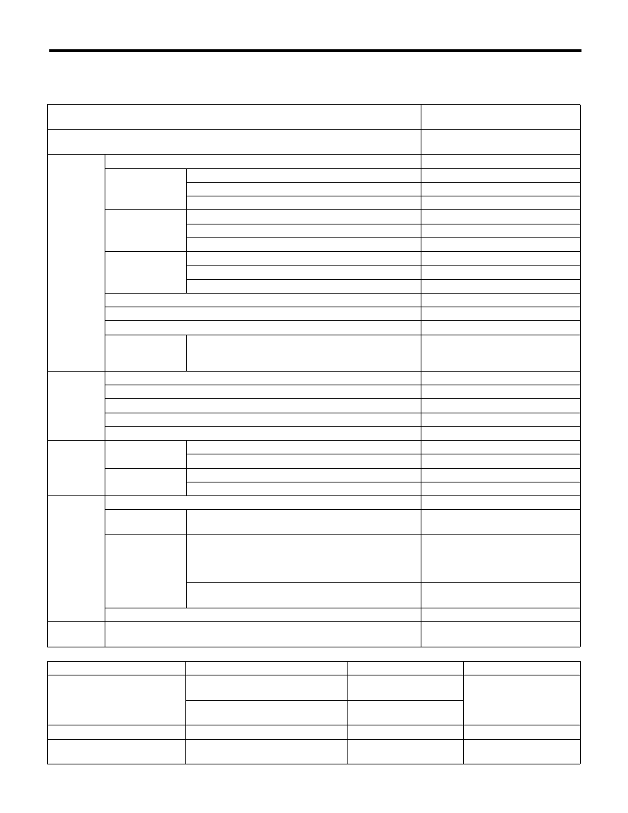
A: SPECIFICATION

Cooling system

Electric fan + Forced engine coolant 

circulation system

Total engine coolant capacity

2 (US qt, Imp qt)

AT: approx. 7.2 (7.6, 6.3)

MT: approx. 7.3 (7.7, 6.4)

Water 
pump

Type

Centrifugal impeller type

Discharge 
performance I

Discharge rate

2 (US gal, Imp gal) /min.

20 (5.3, 4.4)

Pump speed — Discharge pressure

760 rpm — 2.9 kPa (0.3 mAq)

Engine coolant temperature

80°C (176°F)

Discharge 
performance II

Discharge rate

2 (US gal, Imp gal) /min.

100 (26.4, 22.0)

Pump speed — Discharge pressure

3,000 rpm — 49.0 kPa (5.0 mAq)

Engine coolant temperature

80°C (176°F)

Discharge 
performance III

Discharge rate

2 (US gal, Imp gal) /min.

200 (52.8, 44.0)

Pump speed — Discharge pressure

6,000 rpm — 225.4 kPa (23.0 mAq)

Engine coolant temperature

80°C (176°F)

Impeller diameter

mm (in)

76 (2.99)

Number of impeller vanes

8

Pump pulley diameter

mm (in)

60 (2.36)

Clearance 
between impeller 
and case

Standard

mm (in)

0.5 — 1.5 (0.020 — 0.059)

Thermostat

Type

Wax pellet type

Starting temperature to open

76 — 80°C (169 — 176°F)

Fully opens

91°C (196°F)

Valve lift

mm (in)

9.0 (0.354) or more

Valve bore

mm (in)

35 (1.38)

Radiator 
fan

Motor input

Main fan

W

120

Sub fan

W

120

Fan diameter / 
Blade

Main fan

320 mm (12.6 in)/5

Sub fan

320 mm (12.6 in)/7

Radiator

Type

Down flow

Core dimensions

Width × Height × Thickness

mm (in)

687.4 × 340 × 16 

(27.06 × 13.39 × 0.63)

Pressure range in 
which cap valve is 
open

Coolant filler tank side

kPa (kg/cm

2

, psi)

Above: 108

r14.7

(1.1

r0.15, 16r2.1)

Below: –1.0 to –4.9

(–0.01 — –0.05, –0.1 — –0.7)

Radiator side

kPa (kg/cm

2

, psi)

Above only: 137

r14.7

(1.40

r0.15, 20r2.1)

Fins

Corrugated fin type

Reservoir 
tank

Capacity

2 (US qt, Imp qt)

0.45 (0.48, 0.40)


Recommended materials

Item number

Alternative

Coolant

SUBARU SUPER COOLANT 

(Concentrated type)

 — 

 — 

SUBARU SUPER COOLANT 

(Diluted type)

K0670Y0000

Water for dilution

Distilled water

 — 

Soft water or tap water

Cooling system protective 
agent

Cooling system conditioner

SOA345001

 — 

CO(H4DOTC)-3

General Description

COOLING

B: COMPONENT

1. WATER PUMP

(1)

Water pump ASSY

(5)

Gasket

Tightening torque:N·m (kgf-m, ft-lb)

(2)

Gasket

(6)

Thermostat cover

T1: First 12 (1.2, 8.9)

(3)

Heater by-pass hose

(7)

Coolant filler by-pass hose


Second 12 (1.2, 8.9)

(4)

Thermostat

(8)

Clip

T2: 12 (1.2, 8.9)

CO-02417

(6)

(4)

(1)

(5)

(2)

T2

T1

T1

(3)

(7)

(8)

(8)

CO(H4DOTC)-4

General Description

COOLING

2. RADIATOR AND RADIATOR FAN

CO-02499

T2

T3

T2

(27)

(26)

(5)

(5)

(25)

(12)

(11)

(14)

(5)

(1)

(2)

(28)

(5)

(21)

(13)

(24)

(3)

T5

(4)

(5)

(6)

(5)

T3

T4

(9)

(7)

(10)

(8)

(29)

T4

(15)

(15)

(18)

(19)

(20)

B

C

T4

T4

(17)

(16)

(15)

(15)

T4

C

B

(30)

T1

(22)

(23)

CO(H4DOTC)-5

General Description

COOLING

C: CAUTION

• Wear appropriate work clothing, including a cap,
protective goggles and protective shoes when per-
forming any work.
• Remove contamination including dirt and corro-
sion before removal, installation or disassembly.
• Keep the disassembled parts in order and pro-
tect them from dust and dirt.
• Before removal, installation or disassembly, be
sure to clarify the failure. Avoid unnecessary re-
moval, installation, disassembly and replacement.
• Vehicle components are extremely hot after driv-
ing. Be wary of receiving burns from heated parts.
• Be sure to tighten fasteners including bolts and
nuts to the specified torque.
• Place shop jacks or rigid racks at the specified
points.
• Before disconnecting connectors of sensors or
units, be sure to disconnect the ground cable from
battery.
• Prepare a container and cloth to prevent scatter-
ing of engine coolant when performing work where
engine coolant can be spilled. If the fuel spills, wipe
it off immediately to prevent from penetrating into
floor or flowing out for environmental protection.
• Follow all government and local regulations con-
cerning disposal of refuse when disposing engine
coolant.

(1)

Radiator lower cushion

(14)

Radiator main fan ASSY

(26)

Coolant filler tank hose A

(2)

Radiator

(15)

ATF hose clip (AT model)

(27)

Coolant filler tank hose B

(3)

Radiator upper cushion

(16)

ATF hose A (AT model)

(28)

Radiator lower bracket

(4)

Radiator upper bracket

(17)

ATF hose B (AT model)

(29)

Over flow hose B

(5)

Clip

(18)

ATF pipe (AT model)

(30)

Heat shield cover (AT model)

(6)

Radiator inlet hose

(19)

ATF hose C (AT model)


(7)

Engine coolant reservoir tank cap

(20)

ATF hose D (AT model)

Tightening torque:N·m (kgf-m, ft-lb)

(8)

Over flow hose A

(21)

Radiator outlet hose

T1: 3 (0.3, 2.2)

(9)

Engine coolant reservoir tank

(22)

Radiator drain plug

T2: 3.4 (0.3, 2.5)

(10)

Over flow pipe

(23)

O-ring

T3: 5 (0.5, 3.7)

(11)

Radiator sub fan shroud

(24)

Engine coolant filler tank

T4: 7.5 (0.8, 5.5)

(12)

Radiator main fan shroud

(25)

Radiator cap 
(Engine coolant filler tank cap)

T5: 12 (1.2, 8.9)

(13)

Radiator sub fan ASSY


Content   ..  283  284  285  286   ..