Subaru Legacy IV (2008 year). Manual - part 236


  Index      Subaru     Subaru Legacy IV - service repair manual 2008 year


Search            


Content   ..  234  235  236  237   ..


Subaru Legacy IV (2008 year). Manual - part 236


FU(H4DOTC)-47

Front Oxygen (A/F) Sensor

FUEL INJECTION (FUEL SYSTEMS)

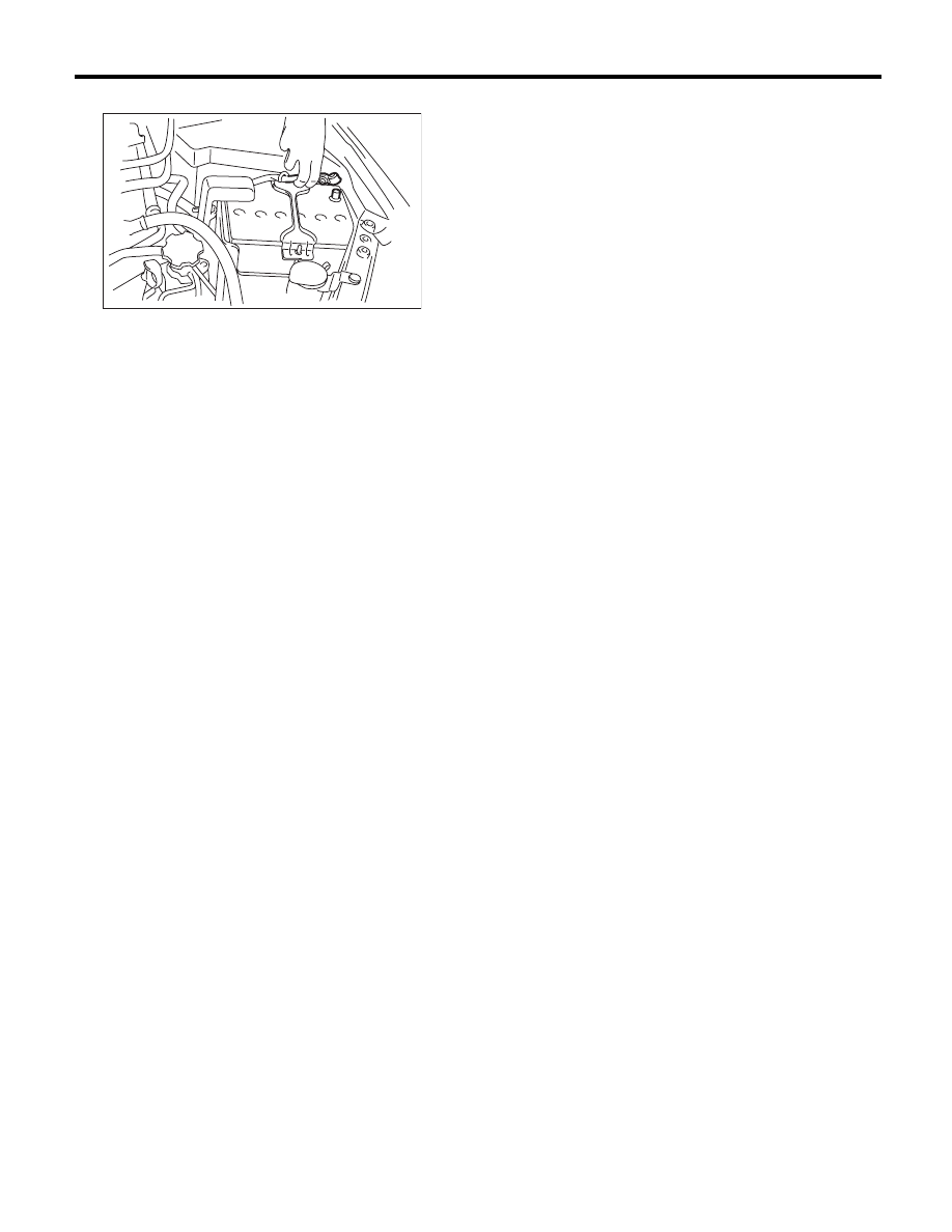
7) Connect the ground cable to battery.

IN-00203

FU(H4DOTC)-48

Rear Oxygen Sensor

FUEL INJECTION (FUEL SYSTEMS)

18.Rear Oxygen Sensor

A: REMOVAL

1) Set the vehicle on a lift.
2) Disconnect the ground cable from battery.

3) Lift up the vehicle.
4) Remove clip (A) holding the rear oxygen sensor
harness. (AT model)
5) Disconnect the connector from the rear oxygen
sensor.
• AT model

• MT  model

6) Apply spray-type lubricant or equivalent to the
threaded portion of rear oxygen sensor, and leave
it for one minute or more.

7) Remove the rear oxygen sensor.

CAUTION:
When removing the rear oxygen sensor, wait
until exhaust pipe cools, otherwise it will dam-
age the exhaust pipe.

B: INSTALLATION

CAUTION:
If lubricant is spilt onto the exhaust pipe, wipe it
off with cloth to avoid emission of smoke or
causing a fire.
1) Before installing rear oxygen sensor, apply the
anti-seize compound only to the threaded portion of
rear oxygen sensor to make the next removal eas-
ier.

CAUTION:
Never apply anti-seize compound to the protec-
tor of rear oxygen sensor.

Anti-seize compound:

NEVER-SEEZ NSN, JET LUBE SS-30 or 
equivalent

2) Install the rear oxygen sensor.

Tightening torque:

21 N·m (2.1 kgf-m, 15.5 ft-lb)

3) Affix the rear oxygen sensor with the clip (A). (AT
model)

IN-00203

EX-02368

(A)

EX-02361

FU-03829

FU-03829

FU(H4DOTC)-49

Rear Oxygen Sensor

FUEL INJECTION (FUEL SYSTEMS)

4) Connect the connector to rear oxygen sensor.
• AT model

• MT  model

5) Lower the vehicle.
6) Connect the ground cable to battery.

EX-02368

(A)

EX-02361

IN-00203

FU(H4DOTC)-50

SI-DRIVE (SUBARU Intelligent Drive) Selector

FUEL INJECTION (FUEL SYSTEMS)

19.SI-DRIVE (SUBARU Intelligent 

Drive) Selector

A: REMOVAL

1) Disconnect the ground cable from battery.

2) Remove the console box. <Ref. to EI-54, RE-
MOVAL, Console Box.>
3) Disconnect the SI-DRIVE selector connector.

4) Remove the screws which secure the SI-DRIVE
selector to the console box.

5) Disconnect the connector from SI-DRIVE selec-
tor cover, and remove the SI-DRIVE selector.

B: INSTALLATION

Install in the reverse order of removal.

C: INSPECTION

Measure the resistance between SI-DRIVE selec-
tor terminals.

IN-00203

FU-04006

FU-04007

FU-04008

Switch position

Terminal No.

Standard

Sport (when turning 

the SI-DRIVE 

selector to the left)

2 and 3

Less than 10 

:

Intelligent (when 

pushing the 

SI-DRIVE selector)

0.8 — 1.2 k

:

Sport Sharp (when 

turning the 

SI-DRIVE selector 

to the right)

2.14 — 3.2 k

:

FU-03123

2

3

4

1

5


Content   ..  234  235  236  237   ..