Subaru Legacy IV (2008 year). Manual - part 152
EN(H4SO)(diag)-211
Diagnostic Procedure with Diagnostic Trouble Code (DTC)
ENGINE (DIAGNOSTICS)
BL:DTC P0456 EVAPORATIVE EMISSION CONTROL SYSTEM LEAK DETECTED
(VERY SMALL LEAK)
DTC DETECTING CONDITION:
• Two consecutive driving cycles with fault
• GENERAL DESCRIPTION <Ref. to GD(H4SO)-126, DTC P0456 EVAPORATIVE EMISSION CONTROL
SYSTEM LEAK DETECTED (VERY SMALL LEAK), Diagnostic Trouble Code (DTC) Detecting Criteria.>
TROUBLE SYMPTOM:
• Fuel odor
• There is a hole of more than 0.5 mm (0.020 in) dia. in evaporation system or fuel tank.
CAUTION:
After repair or replacement of faulty parts, perform Clear Memory Mode <Ref. to EN(H4SO)(diag)-50,
OPERATION, Clear Memory Mode.>, and Inspection Mode <Ref. to EN(H4SO)(diag)-41, PROCEDURE,
Inspection Mode.>.
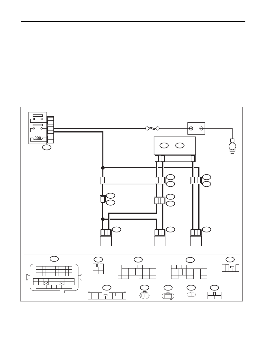
WIRING DIAGRAM:
EN-06840
5
3
6
4
2
1
B47
SBF-7
E4
1
2
E2
B21
41
48
D29
R68
1
2
R213
R15
1
5
R1
B97
14
15
R67
R46
7
6
C17
C28
R144
1
2
B136
C:
B137
D:
3
1
2
4
5
6
B47
R213
E
PURGE CONTROL
SOLENOID VALVE
ECM
DRAIN VALVE
PRESSURE CONTROL
SOLENOID VALVE
MAIN RELAY
BATTERY
B21
E4
1 2
1 2 3 4
12 13 14 15
5 6 7 8
16 17 18 19
9 10 11
20 21 22
23 24 25 26 27 28 29 30 31 32 33
35
34
37
36
39
38
41
40
43
42
44
45
47
46
49
48
51
50
53
52
54
1 2
3
4 5 6 7 8
1 2
R68
1 2
B97
R144
R67
1
2
3 4 5 6
16
10 11 12 13 14 15
25
24
30
9
8
7
17 18 19 20
28
21 22 23
29
32
31
1
2
3
4
5
6
27
26
33 34 35
B136
C:
B137
5
6
7
8
2
1
9
4
3
10
22 23
11 12 13 14 15
24 25
26
16 17
18 19 20 21
27
28 29
30 31
D:
1 2 3 4
5 6 7 8 9
10 11 12 13 14 15 16 17 18 19 20