Subaru Legacy IV (2008 year). Manual - part 1189


  Index      Subaru     Subaru Legacy IV - service repair manual 2008 year


Search            


Content   ..  1187  1188  1189  1190   ..


Subaru Legacy IV (2008 year). Manual - part 1189


WI-8

Basic Diagnostic Procedure

WIRING SYSTEM

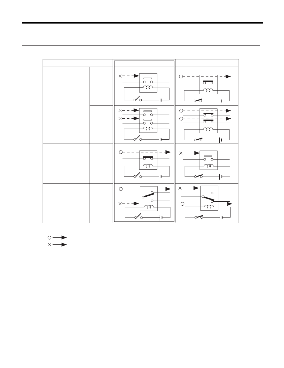
• Relays are classified as normally-open or normally-closed.
The normally-closed relay has one or more contacts. The wiring diagram shows the relay mode when the en-
ergizing circuit is OFF.

WI-16724

Relay type

4-pole

6-pole

4-pole

6-pole

Normally-open type

Normally-closed type

Mixed type

Key to symbols:

: Current flows.

: Current does not flow.

Energizing circuit OFF

Energizing circuit ON

WI-9

Basic Diagnostic Procedure

WIRING SYSTEM

• Each connector number shown in the wiring dia-
gram corresponds to that in the wiring harness. The
location of each connector in the actual vehicle is
determined by reading the first character of the
connector (for example, a “F” for F8, “i” for i16, etc.)
and the type of wiring harness. The first character
of each connector number corresponds to the area
or system of the vehicle.

Symbol

Wiring harness and cord

F

Front wiring harness

B

Bulkhead wiring harness

E

Engine wiring harness

T

Transmission cord

D

Door cord LH & RH, Rear gate cord
Rear door cord LH & RH, Rear defogger cord

i

Instrument panel wiring harness

R

Rear wiring harness,
Fuel tank cord,
Roof cord, Rear gate cord,
Rear defogger ground cord (Sedan model)

AB

Airbag wiring harness

F23

F98

F21

F58

F100

F5

F27

F47

F34

F19

F22

F96

WI-02753

Each connector number 
shown in wiring diagram 
corresponds to that in 
the vehicle.

F19

FRONT TURN  SIGNAL 
LIGHT LH (UPPER)

BG

2

B

1

F22

FRONT TURN  SIGNAL 
LIGHT LH (LOWER)

BG

3

B

2

(GRAY)

F3

(GRAY)

F19

1 2

WI-10

Basic Diagnostic Procedure

WIRING SYSTEM

D: SYMBOLS IN WIRING DIAGRAMS

A number of symbols are used in each wiring diagram to easily identify parts or circuits.

WI-21328

LR

LW

RL

3

7

2

5

MAIN FUSE BOX (M/B)

MB-11

MB-10

F39

P-SUP-02

B

P-SUP-02

A

P-SUP-02

C

No

.3 10A

No

.9 15A

No

.8 15A

SBF-1 100A

HEAD-
LIGHT
RELAY
RH

HEAD-
LIGHT
RELAY
LH

G

P-SUP-04

D

H/L(2L)-01

RL

LW

GR

LB

MB-10

M/B FUSE NO. 8

MB-11

M/B FUSE NO. 9

FB-16

F/B FUSE NO. 11

(IG)

MB-5

HEADLIGHT

RELAY

TO POWER SUPPLY CIRCUIT

LW

4

R

3

YL

LW

R

YL

2

YB

1

RY

2

LW

2

R

1

YL

3

P

LW

B1

R

A1

F44

F45

F23

F7

B61

B62

B

REF TO. 

GND-02

RL

2

R

1

YL

3

B71

B112

LY

8

RY

7

YB

B

17

16

3

17

16

DIMMER &
PASSING SWITCH

UP LOW PASS

HF

HU

HL

E

SMJ

LB

H1

B36

SMJ

DIODE

R4

PARKING
BRAKE
SWITCH

LIGHTING SWITCH

OFF

HC

TC

EL

HEADLIGHT LH

LOW

HIGH

HEADLIGHT RH

LOW

HIGH

REF TO. 

FOG(H4)-01

REF TO. 

FOG(H6)-01

REF TO.  ST(MT)-01 

REF TO.  ST(AT)-01 

B51

A:

B52

C:

F41

G:

FB-37

D4

D7

BG

D11

A2

WR

G4

BL

G1

BR

D10

FB-35

FB-34

1

2 3

4 5 6 7

1 2

3

4 5 6 7 8

LgB

Or

FUSE &
RELAY
BOX (F/B)

i5

B:

B51

A:

B152

D:

B52

C:

B158

E:

F41

G:

F40

F:

FB-36

A3

BG

G7

N

o

.5 10A

(GRAY)

P-SUP-03

H

P-SUP-03

F

P-SUP-04

K

P-SUP-04

J

No

.1 20A

No

.2 15A

SBF-6 30A

LR

2

R

3

L

1

R

3

BW

2

W

SBF-2 50A

SBF-3 50A

SBF-4 50A

F36

F38

F68

P-SUP-04

E

P-SUP-04

M

P-SUP-04

L

P-SUP-03

I

P-SUP-04

G

1 2 3 4
5 6 7 8

F44

B112

1 2

F23

1

2

3

(BLACK)

F7

(BLACK)

RELAY

DIODE

GROUND

SPECIFICATION
CLASSIFICATION

SPECIFICATION

CLASSIFICATION

CONNECTOR SKETCH

FUSE No. & RATING

POWER SUPPLY
ROUTING

WIRE TRACING
ON EXTENDED
WIRING DIAGRAMS

SYMBOLS OF
WIRE
CONNECTION
AND CROSSING

Example

P

P

17

R3

B99

P

P

7

R1

B97

2

LY

13

13

WR

OR

: WITHOUT REAR DEFOGGER

: WITH REAR DEFOGGER

OR

WR

WG

WG

SD

SD

: WAGON

: SEDAN

SD

WG

TWISTED PAIR LINE

CONNECTOR-1

CONNECTOR-2

2

1

WI-11

Basic Diagnostic Procedure

WIRING SYSTEM

1. RELAY

A symbol used to indicate a relay.

2. CONNECTOR 1

The sketch of the connector indicates the one-pole
types.

3. WIRING CONNECTION

Some wiring diagrams are indicated in foldouts for
convenience. Wiring destinations are indicated
where necessary by corresponding symbols.
(When two pages are needed for clear indication)

4. FUSE NO. & RATING

The “FUSE No. & RATING” corresponds with that
used in the fuse box (main fuse box, fuse and joint
box).

5. CONNECTOR 2

• Each connector is indicated by a symbol.
• Each terminal number is indicated in the corre-
sponding wiring diagram in an abbreviated form.
• For example, terminal number “G4” refers to No.
4 terminal of connector (G: F41) shown in the con-
nector sketch.

6. CONNECTOR SKETCH

• Each connector sketch clearly identifies the
shape and color of a connector as well as terminal
locations. Non-colored connectors are indicated in
white or natural color.
• When more than two types of connector number
are indicated in a connector sketch, it means that
the same type connectors are used.

7. GROUND

Each grounding point can be located easily by re-
ferring to the corresponding wiring harness.

8. DIODE

A symbol is used to indicate a diode.

9. WIRE TRACING ON EXTENDED WIRING 
DIAGRAMS

For a wiring diagram extending over at least two
pages, a symbol (consisting of the same characters
with arrows), facilitates wire tracing from one page
to the next.
A

mo A, B mo B

10.SYMBOLS OF WIRE CONNECTION AND 
CROSSING

11.POWER SUPPLY CIRCUIT

A symbol is used to indicate the power supply in
each wiring diagram.
“MB-5”, “MB-6”, etc., which are used as power sup-
ply symbols throughout the text, correspond with
those shown in the “POWER SUPPLY CIRCUIT” in
the wiring diagram.
Accordingly, using the “POWER SUPPLY CIR-
CUIT” and wiring diagrams permits service person-
nel to understand the entire electrical arrangement
of a system.

12.CLASSIFICATION BY SPECIFICATION

When the wiring diagram differ according to vehicle
specifications, the specification difference is de-
scribed by using abbreviations.

13.TWISTED PAIR LINE

The twisted pair line is indicated by a symbol in the
wiring diagrams.

WI-02755

Symbol

Symbol

Refers to wires which are
crossed but not connected.

Refers to wires which are
connected and branched
at the dot point.

WI-16199

TWISTED PAIR LINE

P

V

B25

B26

V

9

P

10


Content   ..  1187  1188  1189  1190   ..