Content .. 1119 1120 1121 1122 ..
Subaru Legacy IV (2008 year). Manual - part 1121
SL-57
Transmitter
SECURITY AND LOCKS
26.Transmitter
A: REMOVAL
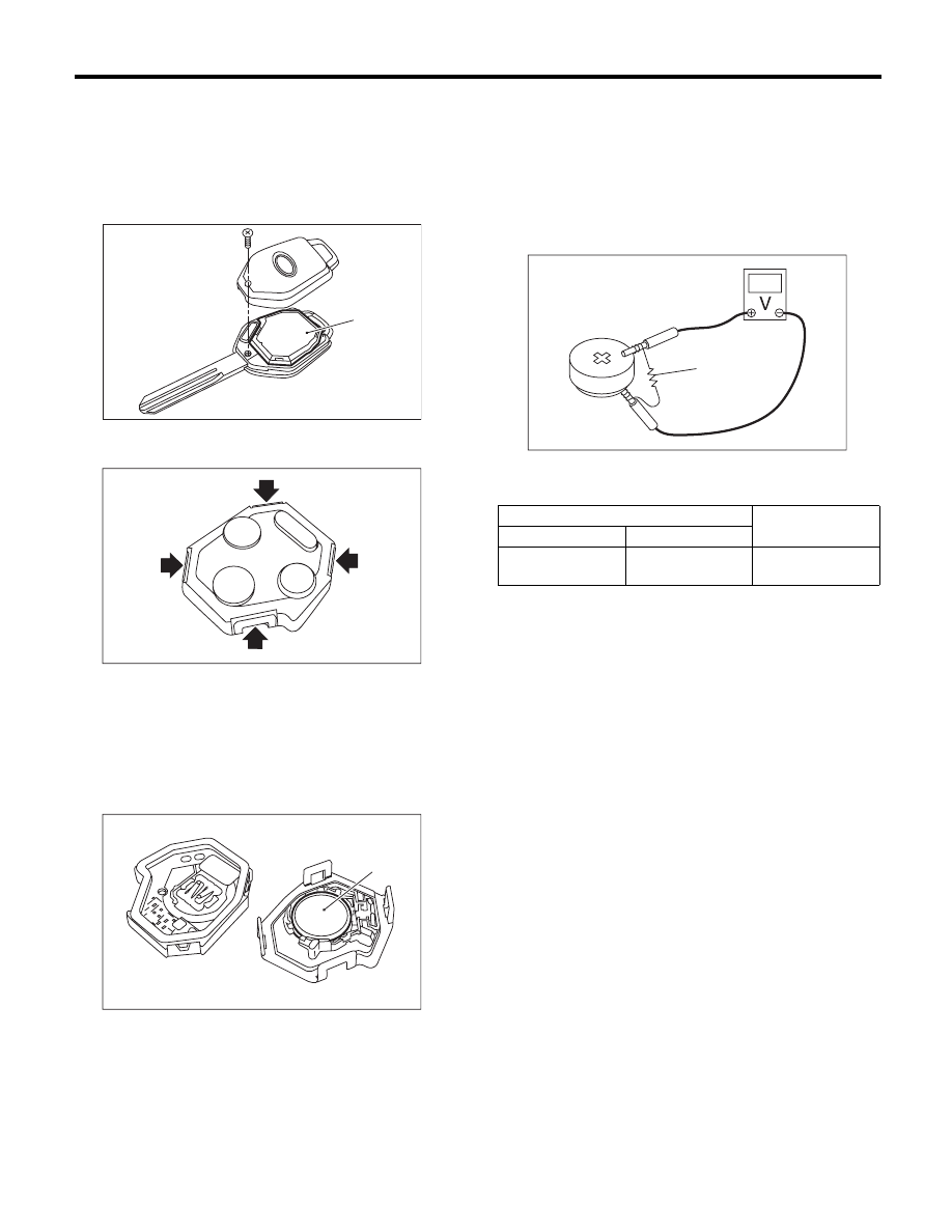
1. TRANSMITTER BATTERY
1) Disassemble the keyless transmitter, and take
out the transmitter case (1).
2) Remove the claw, and open the transmitter
case.
3) Remove the battery (1) from the transmitter.
NOTE:
To prevent static electricity damage to the transmit-
ter printed circuit board, touch the steel area of
building with hand to discharge static electricity car-
ried on body or clothes before disassembling the
transmitter.
B: INSTALLATION
1. TRANSMITTER BATTERY
Install in the reverse order of removal.
C: INSPECTION
1. TRANSMITTER BATTERY
Measure the voltage between the keyless transmit-
ter battery (+) terminal and (–) terminal.
NOTE:
Battery discharge occurs during the measurement.
Complete the measurement within 5 seconds.
If NG, replace the battery. (Use CR1620 or equiva-
lent.)
SL-00957
(1)
SL-00958
SL-00959
(1)
(A) Resistance (47
:)
Tester connection
Standard
(+)
(–)
Battery
Positive terminal
Battery
Ground terminal
2.5 — 3.0 V
SL-00066
(A)