Subaru Legacy IV (2008 year). Manual - part 110


  Index      Subaru     Subaru Legacy IV - service repair manual 2008 year


Search            


Content   ..  108  109  110  111   ..


Subaru Legacy IV (2008 year). Manual - part 110


EN(H4SO)(diag)-43

Inspection Mode

ENGINE (DIAGNOSTICS)

1. PREPARATION FOR THE INSPECTION 
MODE

1) Check battery voltage is more than 12 V and fuel
remains half [20 — 40 

2 (5.3 — 10.6 US gal, 4.4 —

8.8 Imp gal)].
2) Lift up the vehicle using a garage jack and place
it on rigid racks, or drive the vehicle onto free roll-
ers.

WARNING:
• Before lifting up the vehicle, ensure parking
brakes are applied.
• Do not use a pantograph jack in place of a rig-
id rack.
• Secure a rope or wire to the front or rear tow-
ing hooks to prevent the lateral runout of front
wheels.
• Before rotating the wheels, make sure that
there is no one in front of the vehicle. Besides
while the wheels are rotating, make sure that no
one approaches the vehicle front side.
• Make sure that there is nothing around the
wheels. For AWD model, pay special attention
to all four wheels.
• While servicing, do not depress or release
the clutch pedal or accelerator pedal quickly re-
gardless of the engine speed. Quick operation
may cause the vehicle to drop off the free roller.
• To prevent the vehicle from slipping due to
vibration, do not place anything between rigid
rack and the vehicle.

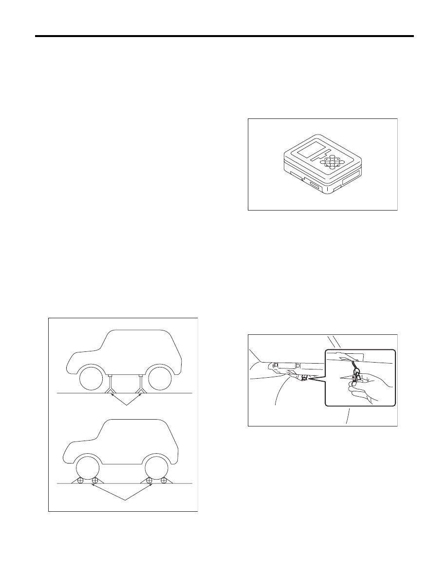
2. SUBARU SELECT MONITOR

1) Check that no DTC remains after clearing mem-
ory. <Ref. to EN(H4SO)(diag)-50, Clear Memory
Mode.>
2) Warm up the engine.
3) Prepare the Subaru Select Monitor kit. <Ref. to
EN(H4SO)(diag)-7, PREPARATION TOOL, Gen-
eral Description.>

4) Prepare PC with Subaru Select Monitor in-
stalled.
5) Connect the USB cable between SDI (Subaru
Diagnosis Interface) and USB port on the personal
computer (dedicated port for the Subaru Select
Monitor).

NOTE:
The dedicated port for the Subaru Select Monitor
means the USB port which was used to install the
Subaru Select Monitor.
6) Connect the diagnosis cable to SDI.
7) Connect the delivery (test) mode connector (A)
located under the glove box.

(A) Rigid rack

(B) Free roller

EN-00041

(A)

(B)

EN-05692

PI-00201

(A)

EN(H4SO)(diag)-44

Inspection Mode

ENGINE (DIAGNOSTICS)

8) Connect SDI to data link connector located in the
lower portion of the instrument panel (on the driv-
er’s side).

CAUTION:
Do not connect the scan tools except for Suba-
ru Select Monitor and general scan tool.
9) Start the PC.
10) Turn the ignition switch to ON (engine OFF)
and run the “PC application for Subaru Select Mon-
itor”.
11) On the «Main Menu» display screen, select the
{Each System Check}.
12) On the «System Selection Menu» display
screen, select the {Engine Control System}.
13) Click the [OK] button after the information of
engine type has been displayed.
14) On the «Engine Diagnosis» display screen, se-
lect the {Dealer Check Mode Procedure}.
15) When the «Perform Inspection (Dealer Check)
Mode?» is shown on the screen, click the [Next]
button.
16) Perform subsequent procedures as instructed
on the display screen.
• If trouble still remains in the memory, the corre-
sponding DTC appears on the display screen.

NOTE:

• For detailed operation procedures, refer to the
“PC application help for Subaru Select Monitor”.
• For details concerning DTC, refer to “List of Di-
agnostic Trouble Code (DTC)”. 
<Ref. to EN(H4SO)(diag)-80, List of Diagnostic
Trouble Code (DTC).>
• Release the parking brake.
• The speed difference between front and rear
wheels may light the ABS warning light, but this
does not indicate a malfunction. When engine
control diagnosis is finished, perform the ABS
memory clearance procedure of self-diagnosis
system. <Ref. to ABS(diag)-20, Clear Memory
Mode.>

3. GENERAL SCAN TOOL

1) After performing the diagnostics and clearing the
memory, check that no DTC remains. <Ref. to
EN(H4SO)(diag)-50, Clear Memory Mode.>
2) Warm up the engine.
3) Connect the delivery (test) mode connector (A)
located under the glove box.

4) Connect the general scan tool to the data link
connector located in the lower portion of the instru-
ment panel (on the driver’ side).

CAUTION:
Do not connect the scan tools except for Suba-
ru Select Monitor and general scan tool.

5) Start the engine.

NOTE:
• Ensure the selector lever is placed in “P” range
before starting. (AT model)
• Depress the clutch pedal when starting engine.
(MT model)
6) Turn the neutral position switch to ON using se-
lect lever or shift lever.
7) Depress the brake pedal to turn the brake switch
ON. (AT model)
8) Keep the engine speed in 2,500 — 3,000 rpm
range for 40 seconds.

EN-02533

PI-00201

(A)

EN-02533

EN(H4SO)(diag)-45

Inspection Mode

ENGINE (DIAGNOSTICS)

9) Place the select lever or shift lever in D position
(AT model) or 1st gear (MT model) and drive the
vehicle at 5 to 10 km/h (3 to 6 MPH).

NOTE:
• For AWD model, release the parking brake.
• The speed difference between front and rear
wheels may light the ABS warning light, but this in-
dicates no malfunctions. When engine control diag-
nosis is finished, perform the ABS memory
clearance procedure of self-diagnosis system.
<Ref. to ABS(diag)-20, Clear Memory Mode.>
10) Using the general scan tool, check DTC and
record the result(s).

NOTE:
• For detailed operation procedures, refer to the
general scan tool operation manual.
• For details concerning DTC, refer to “List of Diag-
nostic Trouble Code (DTC)”. 
<Ref. to EN(H4SO)(diag)-80, List of Diagnostic
Trouble Code (DTC).>

EN(H4SO)(diag)-46

Drive Cycle

ENGINE (DIAGNOSTICS)

12.Drive Cycle

A: PROCEDURE

For the troubleshooting, there are driving patterns described below. Driving in the specified pattern allows to
diagnose malfunctioning items listed below. After the repair of the following trouble items, be sure to drive the
vehicle with the specified drive patterns to check whether the function is resumed correctly.

1. PREPARATION FOR DRIVE CYCLE

1) Check battery voltage is more than 12 V and fuel remains half [20 — 40 

2 (5.3 — 10.6 US gal, 4.4 — 8.8

Imp gal)].
2) After performing the diagnostics and clearing the memory, check that no DTC remains. <Ref. to
EN(H4SO)(diag)-50, Clear Memory Mode.>
3) Disconnect the delivery (test) mode connector.

NOTE:
• Except for the water temperature specified at starting, be sure to carry out the diagnosis after the engine
is warmed up.
• Perform the diagnosis twice if the DTC marked with *. After completing the first diagnosis, stop the engine
and perform second diagnosis in same condition.

2. DRIVE CYCLE A — DRIVE THE VEHICLE WITH 80 KM/H (50 MPH) FOR 20 MINUTES, AND 
THEN IDLE THE ENGINE FOR A MINUTE

DTC

Item

Condition

*P0125

Insufficient Coolant Temperature for Closed Loop Fuel Control

Coolant temperature at start is less than 20°C 
(68°F).

*P0128

Coolant Thermostat (Engine Coolant Temperature Below Ther-
mostat Regulating Temperature)

 — 

*P0133

O2 Sensor Circuit Slow Response (Bank 1 Sensor 1)

 — 

*P0171

System Too Lean (Bank 1)

Complete diagnosis with drive cycle B or C as well.

*P0172

System Too Rich (Bank 1)

Complete diagnosis with drive cycle B or C as well.

*P0196

Engine Oil Temperature Sensor Circuit Range/Performance

 — 

*P0301

Cylinder 1 Misfire Detected

Complete diagnosis with drive cycle B or C as well.

*P0302

Cylinder 2 Misfire Detected

Complete diagnosis with drive cycle B or C as well.

*P0303

Cylinder 3 Misfire Detected

Complete diagnosis with drive cycle B or C as well.

*P0304

Cylinder 4 Misfire Detected

Complete diagnosis with drive cycle B or C as well.

*P0420

Catalyst System Efficiency below Threshold (Bank 1)

 — 

*P0442

Evaporative Emission Control System Leak Detected 
(Small Leak)

Engine coolant temperature at engine start is less 
than 30°C (86°F).

*P0451

Evaporative Emission Control System Pressure Sensor

 — 

*P0456

Evaporative Emission Control System Leak Detected 
(Very Small Leak)

Engine coolant temperature at engine start is less 
than 30°C (86°F).

*P0457

Evaporative Emission Control System Leak Detected 
(Fuel Cap Loose/Off)

Engine coolant temperature at engine start is less 
than 30°C (86°F).

*P0459

Evaporative Emission System Purge Control Valve Circuit High

 — 

P1443

Vent Control Solenoid Valve Function Problem

 — 

*P2096

Post Catalyst Fuel Trim System Too Lean (Bank 1)

Complete diagnosis with drive cycle B or C as well.

*P2097

Post Catalyst Fuel Trim System Too Rich (Bank 1)

Complete diagnosis with drive cycle B or C as well.

P2103

Throttle Actuator Control Motor Circuit High

Complete diagnosis with drive cycle B or C as well.


Content   ..  108  109  110  111   ..