Subaru Legacy IV (2008 year). Manual - part 1009


  Index      Subaru     Subaru Legacy IV - service repair manual 2008 year


Search            


Content   ..  1007  1008  1009  1010   ..


Subaru Legacy IV (2008 year). Manual - part 1009


AB(diag)-24

Subaru Select Monitor

AIRBAG SYSTEM (DIAGNOSTICS)

7. Subaru Select Monitor

A: OPERATION

1. READ DIAGNOSTIC TROUBLE CODE 
(DTC)

When malfunction of airbag system occurs, the
DTC stored in airbag control module will be read
out.
1) Prepare the Subaru Select Monitor kit. <Ref. to
AB(diag)-8, SPECIAL TOOL, PREPARATION
TOOL, General Description.>
2) Connect the diagnosis cable to Subaru Select
Monitor.
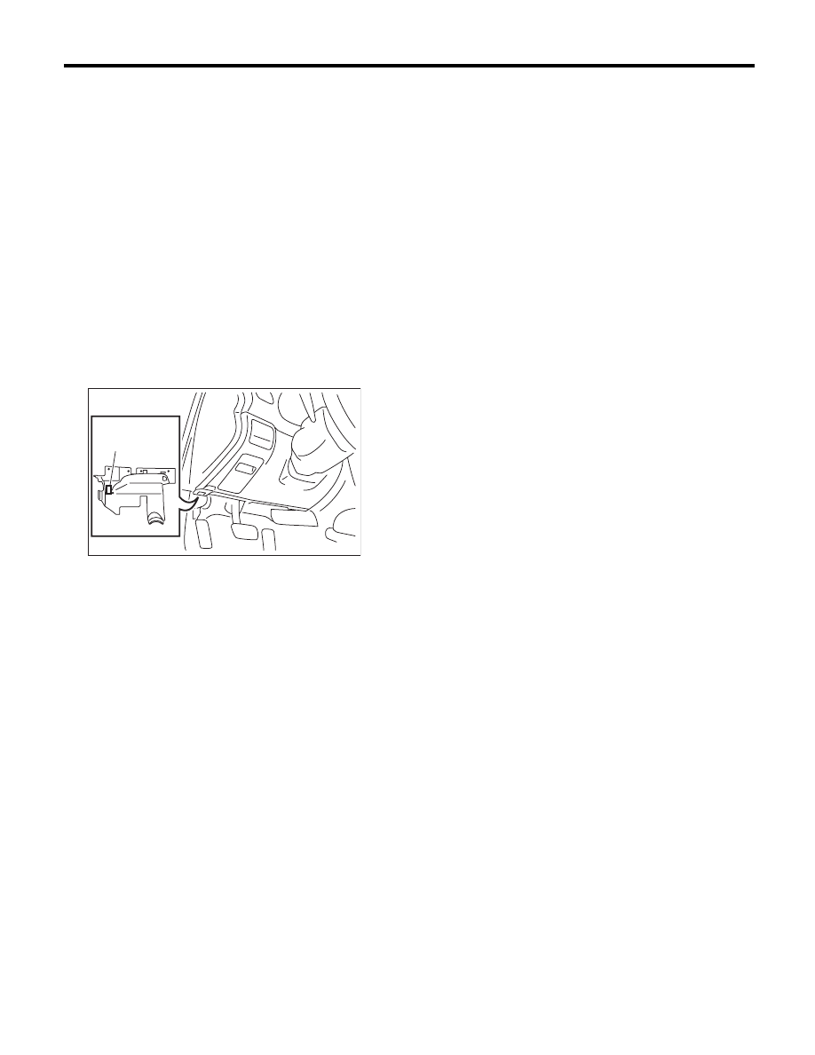
3) Connect the Subaru Select Monitor to data link
connector.

(1) Data link connector is located in the lower
portion of instrument panel (on the driver’s
side).

(2) Connect the diagnosis cable to data link
connector.

CAUTION:
Do not connect scan tools other than the Suba-
ru Select Monitor.
4) Turn the ignition switch to ON (engine OFF) and
run the Subaru Select Monitor.
5) On the «Main Menu» display, select the {Each
System Check}.
6) On the «System Selection Menu» display, select
the {Airbag System}.
7) After {Airbag System} is displayed, select [OK].
8) Select the {Diagnostic Code(s) Display} in «Air-
bag System».

NOTE:
• For detailed operation procedure, refer to the
“PC application help for Subaru Select Monitor”.
• For details concerning DTCs, refer to List of Di-
agnostic Trouble Code (DTC). <Ref. to AB(diag)-
38, List of Diagnostic Trouble Code (DTC).>

(1) Data link connector

ABS00465

(1)

AB(diag)-25

Subaru Select Monitor

AIRBAG SYSTEM (DIAGNOSTICS)

2. DISPLAY OF STATUS INFORMATION

Check the operating condition of each sensor in the event of malfunction in the seat belt buckle switch, or
when the seat belt buckle switch has been replaced.
1) On the «Main Menu» display, select the {Each System Check}.
2) On the «System Selection Menu» display, select the {Airbag System}.
3) On the «Airbag System» display, select the {Status Data}.
The following table is for support data.

*1: The seat position is forward.
*2: The seat position is rearward.
*3: Displayed when data other than before and behind the seat, such as the breakdown etc, is input.
*4: Displayed when it is initial.
*5: Seat position sensor not supported
*6: Seat belt fastened
*7: Seat belt not fastened
*8: Displayed when data other than belt fastened or not fastened, such as breakdowns is input.
*9: Seat belt buckle switch not supported
*10: Passenger’s airbag operating state
*11: Passenger’s airbag non-operating state

NOTE:
For detailed operation procedure, refer to the “PC application help for Subaru Select Monitor”.

3. CLEAR MEMORY MODE

Clear the DTC stored in the airbag control module after repairing the airbag system. (After the breakdown is
recovered, the breakdown code for completed recoveries are read out when the next breakdown occurs if the
memory clear work is not performed.)
1) On the «Main Menu» display, select the {Each System Check}.
2) On the «System Selection Menu» display, select the {Airbag System}.
3) Select the {Clearing Memory} in «Airbag System».
4) When the “Clear Memory?” is shown on the screen, click the [OK] button.
5) When “Done” is displayed, end the Subaru Select Monitor.

NOTE:
For detailed operation procedure, refer to the “PC application help for Subaru Select Monitor”.

Contents

Display Contents

Seat position sensor LH

––

*5

Seat position sensor RH

––

*5

Seat belt buckle switch LH

––

*9

Seat belt buckle switch RH

Belted 

*6

/Unbelted

*7

 /Other 

*8

/Initial Setting 

*4

 /––

*9

Passenger’s airbag control status

ON 

*10

/OFF 

*11

 /Initial Setting 

*4

AB(diag)-26

Subaru Select Monitor

AIRBAG SYSTEM (DIAGNOSTICS)

B: INSPECTION

1. COMMUNICATION FOR INITIALIZING IMPOSSIBLE

DETECTING CONDITION:
Defective harness connector
TROUBLE SYMPTOM:
Communication is impossible between the airbag control module and the Subaru Select Monitor.
WIRING DIAGRAM:

1 2 3 4 5 6 7 8

9 10 11 12 13++

14 15 16

1 2

3 4

5 6 7 8 9 10

MAIN SBF

SBF-6

No.25

B40

B31

AB1

E

16

7

No.13

8

AB6

E

E

16

26

25

21

AB1

B40

AB6

AB-01759

18 19 20

21 22 23 24 25 26 27 28

1 2 3

5 6 7 8

10

9

4

11 12 13 14

16 17

15

29 30

IGNITION
SWITCH

DATA LINK 
CONNECTOR

BATTERY

AIRBAG CONTROL MODULE

AB(diag)-27

Subaru Select Monitor

AIRBAG SYSTEM (DIAGNOSTICS)

Step

Check

Yes

No

1

CHECK IGNITION SWITCH.

Is the ignition switch ON?

Go to step 2.

Turn the ignition 
switch to ON, and 
select the airbag 
mode using the 
Subaru Select 
Monitor.

2

CHECK BATTERY.
1) Turn the ignition switch to OFF.
2) Measure the battery voltage.

Is the voltage 11 V or more?

Go to step 3.

Charge or replace 
the battery.

3

CHECK BATTERY TERMINAL.

Is there poor contact at battery 
terminal?

Repair or tighten 
the battery termi-
nal.

Go to step 4.

4

CHECK SUBARU SELECT MONITOR COM-
MUNICATION.
1) Turn the ignition switch to ON.
2) Using the Subaru Select Monitor, check 
whether communication to other systems can 
be executed normally.

Is the system name displayed 
on Subaru Select Monitor?

Go to step 10.

Go to step 5.

5

CHECK FUSE NO. 25 (IN FUSE & RELAY 
BOX).
Remove the fuse No. 25 and perform visual 
inspection.

Is the fuse No. 25 (in fuse & 
relay box) blown out?

Replace the fuse 
No. 25. If fuse No. 
25 is blown out 
again, check the 
power supply cir-
cuit.

Go to step 6.

6

CHECK AIRBAG CONTROL MODULE CON-
NECTOR.
1) Turn the ignition switch to OFF, disconnect 
the battery ground cable, and wait for 20 sec-
onds or more.
2) Confirm that the connectors of airbag con-
trol module (AB6, AB17, and AB18) are 
securely connected.

Is the connector of the airbag 
control module securely con-
nected?

Go to step 7.

Connect the con-
nector of the airbag 
control module.

7

CHECK SUBARU SELECT MONITOR COM-
MUNICATION.
1) Turn the ignition switch to OFF.
2) Disconnect the airbag control module con-
nector.
3) Turn the ignition switch to ON.
4) Check whether communication to other sys-
tems can be executed normally.

Is the system name displayed 
on Subaru Select Monitor?

Replace the airbag 
control module. 
<Ref. to AB-20, 
Airbag Control 
Module.>

Go to step 8.

8

CHECK HARNESS CONNECTOR BETWEEN 
EACH CONTROL MODULE AND DATA LINK 
CONNECTOR.
1) Turn the ignition switch to OFF.
2) Disconnect the airbag control module, 
ABSCM&H/U, ECM and TCM.
3) Measure the resistance between data link 
connector and chassis ground.

Connector & terminal

(B40) No. 7 — Chassis ground:

Is the resistance 1 M

: or 

more?

Go to step 9.

Repair the harness 
and connector 
between each con-
trol module and 
data link connec-
tor. (Replace the 
entire harness if 
repair is necessary 
for airbag harness.

9

CHECK OUTPUT SIGNAL TO THE AIRBAG 
CONTROL MODULE.
1) Turn the ignition switch to ON in the condi-
tion of step 8.
2) Measure the voltage between data link con-
nector and chassis ground.

Connector & terminal

(B40) No. 7 (+) — Chassis ground (–):

Is the voltage less than 1 V?

Go to step 10.

Repair the harness 
and connector 
between each con-
trol module and 
data link connec-
tor. (Replace the 
entire harness if 
repair is necessary 
for airbag harness.


Content   ..  1007  1008  1009  1010   ..