Subaru Legacy IV (2008 year). Manual - part 26


  Index      Subaru     Subaru Legacy IV - service repair manual 2008 year


Search            


Content   ..  24  25  26  27   ..


Subaru Legacy IV (2008 year). Manual - part 26


PM-44

Suspension

PERIODIC MAINTENANCE SERVICES

20.Suspension

A: INSPECTION

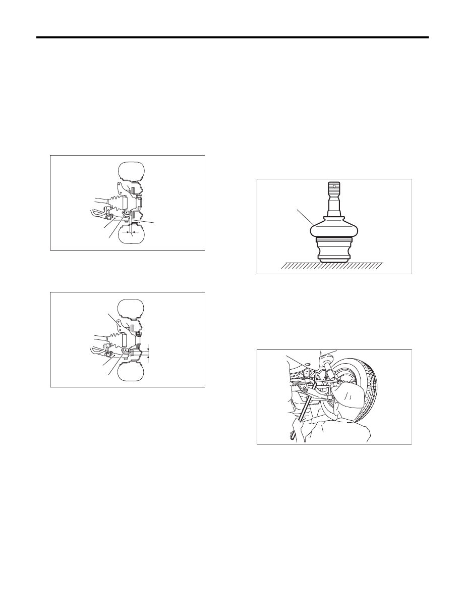
1. SUSPENSION BALL JOINT

1) Jack-up the vehicle until front wheels are off
ground.
2) Grasp the bottom of tire and move it in and out in
axial direction. If relative movement (B) is observed
between the brake disc cover (A) and the end of
front arm (D), ball joint (C) may be excessively
worn.

3) Grasp the end of front arm and move it up and
down. Relative movement (A) between the housing
(D) and front arm (C) boss indicates ball joint (B)
may be excessively worn.

4) If relative movement is observed in the step 2),
3), remove and inspect the ball joint. If the free play
exceeds standard value, replace the ball joint.
<Ref. to FS-16, Front Ball Joint.>

5) Damage of dust seal
Visually inspect the ball joint dust seal. If it is dam-
aged, remove the front arm. <Ref. to FS-18, Front
Arm.> Also, measure the free play of the ball joint.
<Ref. to FS-16, Front Ball Joint.>

(1) If the free play exceeds standard value, re-
place the ball joint.
(2) If the dust seal is damaged, replace with a
new ball joint.

NOTE:
When the front arm ball joint has been removed or
replaced, check the toe of front wheel. If the front
wheel toe-in is not at the specified value, adjust the
toe-in. <Ref. to FS-6, Wheel Alignment.>

2. FRONT, REAR SUSPENSION BUSHING

Apply pressure with tire lever etc. to inspect the
bushing for abnormal fatigue or damage. Replace
the bushings if there is abnormal fatigue or dam-
age.

PM-00057

(A)

(B)

(C)

(D)

PM-00058

(A)

(B)

(C)

(D)

(A) Dust seal

PM-00059

(A)

PM-00180

PM-45

Suspension

PERIODIC MAINTENANCE SERVICES

3. WHEEL ARCH HEIGHT

1) Unload the cargoes and set the vehicle in curb
weight (empty) condition.
2) Check the wheel arch height of the front and rear
suspensions to ensure that they are within speci-
fied values. <Ref. to FS-6, Wheel Alignment.>
3) When the wheel arch height is out of standard,
visually inspect following components and replace
deformed parts.
• Suspension components [Front strut assembly
and rear damper assembly]
• Parts connecting suspension and body
4) When no components are deformed, adjust
wheel arch height by replacing coil spring in the
suspension whose wheel arch height is out of stan-
dard. <Ref. to FS-6, Wheel Alignment.> <Ref. to
RS-7, Wheel Alignment.>

4. WHEEL ALIGNMENT OF FRONT 
SUSPENSION

1) Check the alignment of front suspension to en-
sure that following items conform to standard val-
ues.
• Toe-in
• Camber
• Caster
• Steering angle
<Ref. to FS-6, Wheel Alignment.>
2) When the caster angle does not conform to ref-
erence obviously, visually inspect the following
components and replace deformed parts.
• Suspension components [Strut assembly, cross-
member, front arm, etc.]
• Parts connecting suspension and body
3) When the toe-in and camber are out of standard
value, adjust them so that they conform to standard
value.
4) When the right-and-left turning angles of tire are
out of standard, adjust to standard value.

5. WHEEL ALIGNMENT OF REAR 
SUSPENSION

1) Check the alignment of rear suspension to en-
sure that following items are within standard val-
ues.
• Toe-in
• Camber
• Thrust angle
<Ref. to RS-7, Wheel Alignment.>
2) When the camber angle does not conform to
standard value, visually inspect the following com-
ponents. If the deformation is observed, replace the
damaged parts.
• Suspension components [Shock absorber, front
link, rear link, upper link, rear arm, sub frame, etc]
• Parts connecting suspension and body

3) When the toe-in and thrust angle are out of stan-
dard value, adjust them so that they conform to
standard value.

6. OIL LEAKAGE OF STRUT AND SHOCK 
ABSORBER

Visually inspect the front strut and rear shock ab-
sorber for oil leakage. Replace the front strut and
rear shock absorber if oil leaks excessively.

7. TIGHTNESS OF BOLTS AND NUTS

Check the bolts and nuts for looseness. Retighten
the bolts and nuts to specified torque. If the self-
locking nuts and bolts are removed, replace them
with new parts.
• Front suspension
<Ref. to FS-3, COMPONENT, General Descrip-
tion.>
• Rear suspension
<Ref. to RS-3, COMPONENT, General Descrip-
tion.>

8. DAMAGE TO SUSPENSION PARTS

Check the following parts and the fastening portion
of the vehicle body for deformation or excessive
rusting which impairs the suspension. If necessary,
replace the damaged parts with new parts. If minor
rust formation, pitting, etc. are noted, remove the
rust and take rust prevention measure.
• Front suspension

• Front arm
• Crossmember
• Strut

• Rear suspension

• Sub frame
• Front link
• Rear  link
• Upper link
• Rear  arm
• Shock absorber

• In the area where salt is sprayed to melt snow on
a road in winter, check suspension parts for dam-
age caused by rust every 12 months after lapse of
60 months. Take rust prevention measures as re-
quired.

PM-46

Wheel Bearing

PERIODIC MAINTENANCE SERVICES

21.Wheel Bearing

A: INSPECTION

1. FRONT WHEEL BEARING

NOTE:
Inspect the condition of front wheel bearing grease.
1) Jack-up the front side of vehicle.
2) While holding the front wheel by hand, swing it in
and out to check bearing free play.
3) Loosen the wheel nuts, and remove the front
wheel.
4) If the bearing free play exists in step 2) above,
attach a dial gauge to the hub and measure axial
play in axial direction.

Service limit:

Straight-ahead position within 0.05 mm 
(0.0020 in)

5) Remove the bolts and self-locking nuts, and ex-
tract the front arm from front crossmember.
6) Remove the PTJ of front drive shaft from trans-
mission. <Ref. to DS-13, Front Axle.>
7) While supporting the front drive shaft horizontal-
ly with one hand, turn the hub with the other hand to
check for noise or binding.
If the hub is noisy or binds, replace the front axle.

2. REAR WHEEL BEARING

1) Jack-up the rear side of vehicle.
2) While holding the rear wheel by hand, swing it in
and out to check bearing free play.
3) Loosen the wheel nuts, and remove the rear
wheel.
4) If the bearing free play exists in step 2) above,
attach a dial gauge to the hub and measure axial
play in axial direction.

Service limit:

Straight-ahead position within 0.05 mm 
(0.0020 in)

5) Remove the DOJ of rear drive shaft from rear dif-
ferential. <Ref. to DS-26, Rear Drive Shaft.>
6) While supporting the rear drive shaft horizontally
with one hand, turn the hub with the other hand to
check for noise or binding.
If the hub is noisy or binds, replace the rear axle.

PM-00173

PM-00173

PM-47

Axle Boots & Joints

PERIODIC MAINTENANCE SERVICES

22.Axle Boots & Joints

A: INSPECTION

1. FRONT AND REAR AXLE BOOTS

Inspect the front axle boots (A) and rear axle boots
(B) for deformation, damage or failure. If faulty, re-
place with new part. <Ref. to DS-22, Front Drive
Shaft.> <Ref. to DS-26, Rear Drive Shaft.>
• Front

• Rear

2. PROPELLER SHAFT

Inspect the propeller shaft for damage or failure. If
faulty, replace with new part. <Ref. to DS-10, Pro-
peller Shaft.>

PM-00174

(A)

PM-00175

(B)


Content   ..  24  25  26  27   ..