SsangYong Rexton. Manual - part 554


  Index      SsangYong     SsangYong Rexton - service repair manual


Search            


Content   ..  552  553  554  555   ..


SsangYong Rexton. Manual - part 554


AUTOMATIC TRANSMISSION  5A-191

SSANGYONG  Y200

KAA5A1GO

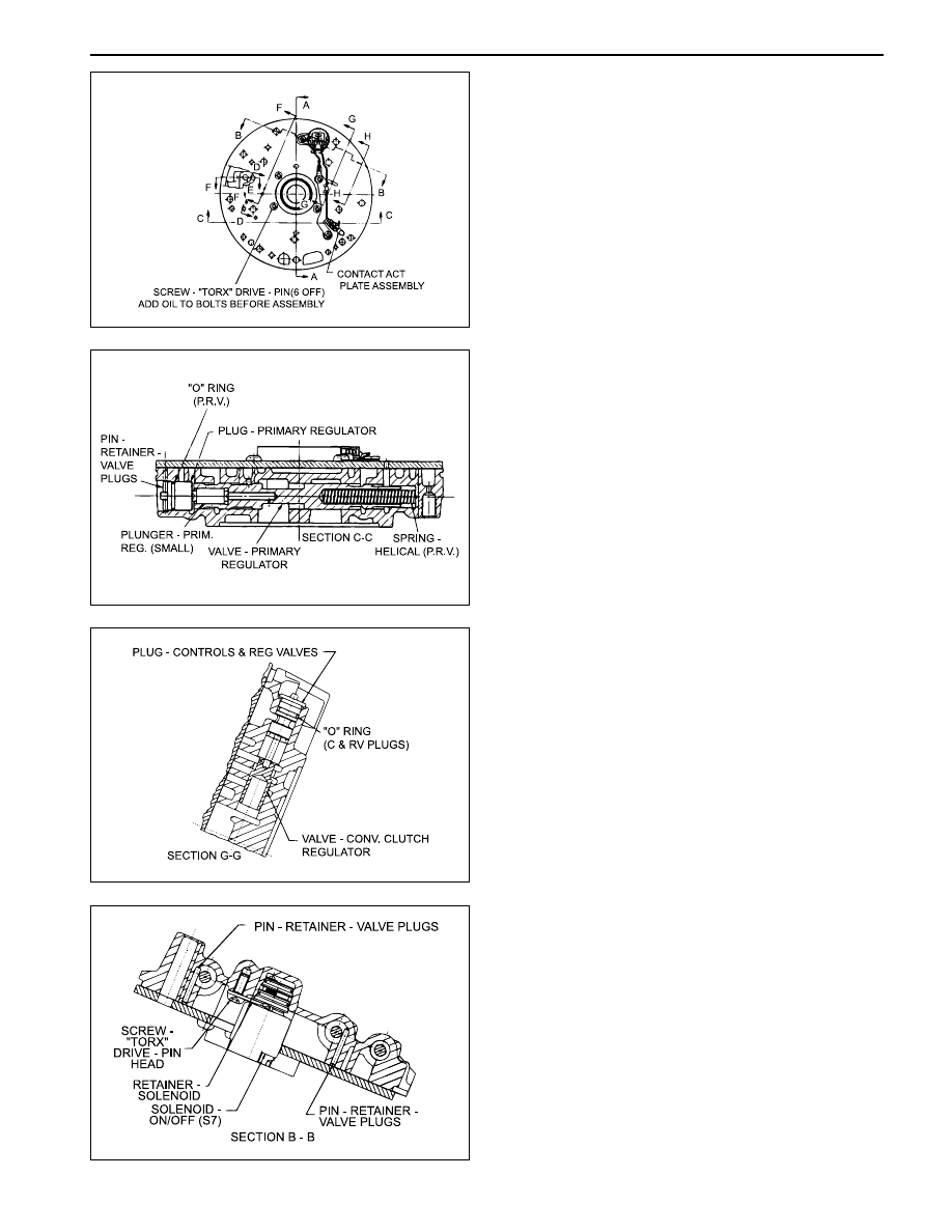
11. Install the converter clutch regulator valve, plug,

spring and ‘O’ ring.

12. Install the retaining pin.

9. Assemble the primary regulator valve, spring and

plunger to the pump cover, ensuring that the
regulator valve slides freely, then fit the regulator
valve plug and ‘O’ ring.

10. Install the retaining pin.

KAA5A1F0

KAA5A1G0

KAA5A1E0

7. Ensure that the pump cover cavities, ports and

holes are clean and free of any obstruction.

8. L u b r i c a t e   a l l   l o o s e   p a r t s   w i t h   a u t o m a t i c

transmission fluid prior to assembly.

KAA5A1D0

5A-192  AUTOMATIC TRANSMISSION

SSANGYONG  Y200

KAA5A1J0

KAA5A1K0

15. Install the converter release check ball and spring.

16. Install the gasket on the pump cover.

17. Install the cover plate, solenoid 7 with the retainer

and the solenoid wiring retainer to the pump cover,
ensuring that the periphery of the cover plate is
flush with the periphery of the pump cover.

18. Tighten the screws to specification in the order.

 (1-5)

Installation Notice

19. Tighten the solenoid 7 screw.

Installation Notice

Tightening Torque

13-16 N•m (10-12 lb-ft)

Check that neither the wiring nor the connector
p r o t r u d e s   e x c e s s i v e l y ,   i n   o r d e r   t h a t   a t
assembly neither the wiring and the connector
contacts or rubs on the input shaft or the C1/
C2 clutch cylinder.

13. Install the converter clutch control valve, spring,

plug, and ‘O’ ring.

14. Install the retaining pin.

KAA5A1H0

Tightening Torque

13-16 N•m (10-12 lb-ft)

AUTOMATIC TRANSMISSION  5A-193

SSANGYONG  Y200

KAA5A1L0

20. Assemble the pump to the pump cover.

21. Tighten all bolts and the crescent screw finger

tight, ensuring that the pump is flush against the
pump cover. Tighten the bolts and the screw to
specification in the order. (A-F)

Installation Notice

22. Install the pump to transmission case gasket onto

the case.

23. Fit the ‘O’ ring to the pump cover outer diameter.

KAA5A1N0

KAA5A1M0

25. Check that the transmission end float is 0.50 -

0.65 mm. If the unshimmed end float clearance is
greater than specification, shims are to be placed
between the No. 4 bearing and the input shaft
bearing surface. If the end float clearance is less
than 0.5 mm then the transmission has been
assembled incorrectly or the parts are out of
specification.

26. Perform the following steps to check the end float :

a. Attach a dial indicator to the front of the trans-

mission case with the stylus resting on the end
of the input shaft.

b. Apply a force of approximately 250 N or 25 kg

to the input shaft.

c. Zero the dial indicator.

d. Place a small lever behind the forward clutch

cylinder and lever the cylinder forward.

e. The measurement recorded on the dial indicator

is the transmission end float or clearance be-
tween the No.4 bearing and the converter sup-
port tube.

27. On completion of this procedure, adjust the front

and rear bands to specifications. Refer to “Front
and Rear Band Adjustment” in this section.

24. Install the pump and cover assembly over the

input shaft being careful not to damage the sealing
rings. Apply additional Loctite 202 or equivalent
as required to the pump cover to case bolts. Install
and tighten bolts to specification.

Installation Notice

Tightening Torque

24-34 N•m (18-25 lb-ft)

Tightening

Torque

Bolt (A-E) : 24-27 N•m (18-20 lb-ft)

Screw (F) : 13-16 N•m (10-12 lb-ft)

5A-194  AUTOMATIC TRANSMISSION

SSANGYONG  Y200

Valve Body

Notice:

Do not wash the nose of solenoids in solvent.

Be aware of ball positions in the upper valve body.

Be aware of 1-2 and 3-4 shift valve positions, they
can be swapped.

Check the 4-3 sequence valve and spring
orientation.

Check that the 12 mm ball is in the lower body.

Check the line pressure relief valve for swarf, and
be aware of replacing the shims.

When servicing the transmission, ensure that the
solenoid 5 damper spring is not broken.

Locate the detent spring central to the detent lever.

Wash the upper and lower valve bodies thoroughly
with cleansing solvent and blow dry.

Check the valve body cavities, ports and holes for
damage or obstructions.

The orifices in the valve body are for stability and
safeguard. Do not drill them larger.

Thoroughly wash all loose components.

Check that all valves slide freely in their location.

1. Install the detent lever locating pin

2. Install the Band Apply Regulator (BAR) valve,

springs, plunger and retaining pin.

3. Install the line pressure relief valve, tapered end

first, spring and disc. Secure with the retaining pin.

KAA5A1O0

KAA5A1P0


Content   ..  552  553  554  555   ..