SsangYong Rexton. Manual - part 547


  Index      SsangYong     SsangYong Rexton - service repair manual


Search            


Content   ..  545  546  547  548   ..


SsangYong Rexton. Manual - part 547


AUTOMATIC TRANSMISSION  5A-163

SSANGYONG  Y200

KAA5A500

KAA5A510

DISASSEMBLY PROCEDURE

Transmission

Tools Required

0555-336256 Transmission Bench Cradle

0555-336257 Pump Puller

Notice:

Remove the inhibitor switch before washing the
transmission in solvent or hot wash.

It is assumed that the transmission fluid has been
drained when the transmission was removed from
the vehicle and that the ’special tools’ quoted are
available.

The transmission is dismantled in a modular fashion,
and the details of disassembly for each module are
given under the appropriate subject. Refer to
Special Tools Table in this chapter for details of all
special 

t o o l s   r e q u i r e d   w h e n   p e r f o r m i n g

disassembly procedures.

Technicians overhauling these transmissions will
also  require a selection of good quality Torx bit
sockets, in particular numbers 30, 40 and 50, and
an 8mm, 10mm and 12 mm double hex socket.

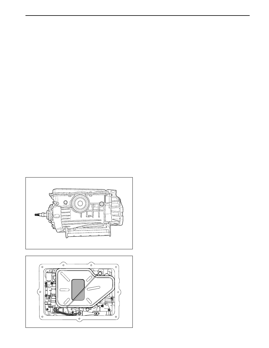
1. Remove the converter and the converter housing.

2. Mount the transmission on the transmission bench

cradle 0555-336256.

3. Remove the oil pan and the oil pan seal.

4. Remove each end of the filter retaining clip from

the valve body and remove the filter.

5. Disconnect the wires from each solenoid and ground

and lay the wiring to one side.

6. Remove the valve body securing screws and

remove the valve body from the case.

5A-164  AUTOMATIC TRANSMISSION

SSANGYONG  Y200

7. Remove the front servo cover circlip.

8. Remove the front servo cover, piston and spring.

Notice:  The plastic servo block is retained by the
piston return spring only.

9. Remove the adaptor housing bolts and adaptor

housing.

10. Remove the pump to case bolts using a multi-hex

8 mm spanner.

11. Using the pump puller 0555-336257, remove the

pump and pump cover.

12. Remove the input shaft, forward clutch cylinder,

a n d   t h e   o v e r d r i v e   s h a f t   a s   a n   a s s e m b l y ,
withdrawing them through the front of the case.

13. Remove the C3 clutch cylinder and sun gears.

14. Remove the front band struts. Remove the front

band.

KAA5A520

KAA5A550

KAA5A530

KAA5A540

AUTOMATIC TRANSMISSION  5A-165

SSANGYONG  Y200

15. Remove the two centre support retaining bolts

using a T50 Torx bit.

16. Remove the centre support retaining circlip.

Notice: Do not hammer the output shaft to remove
the centre support as this will cause permanent
damage to the thrust bearing surfaces.

17. Remove the centre support, 1-2 one way clutch,

and planetary gear set as an assembly.

18. Remove the parking rod cam plate using a T40

Torx bit.

19. Remove the rear band struts and remove the band.

Notice:  Vise the both end of rear band using the
plier and lean forward about 15 degrees

20. Remove the output shaft assembly.

Transmission Case

Tools Required

0555-336258

Cross Shaft Pin Remover/Installer
(Detent Lever)

0555-336261

Cross Shaft Seal Remover

0555-336265

Cross Shaft Pin Remover/Installer
(Inhibitor Switch)

1. Remove the pin from the side of cross shaft

inhibitor switch using cross shaft pin remover/
installer (inhibitor switch) 0555-336265.

2. Remove the inhibitor switch bolts and inhibitor

switch from the case.

3. Remove the cross shaft seals with cross shaft seal

remover 0555-336261.

4. Remove the circlip from the cross shaft. Pull the

shaft to release the drive pin from the selector
quadrant.

KAA5A560

KAA5A570

KAA5A580

KAA5A590

5A-166  AUTOMATIC TRANSMISSION

SSANGYONG  Y200

KAA5A610

KAA5A620

KAA5A630

KAA5A600

5. Using cross shaft pin remover/installer (detent le-

ver) 0555-336258, press the pin from the cross
shaft and withdraw the shaft from the case.

6. Remove the cross shaft pin and spring.

7. Remove the manual valve lever and the park rod.

8. Depress the tangs and withdraw the 10 pin

connector into the case. Remove the wiring loom
assembly.

9. Detach the No.7 solenoid wire from the front of

the case.

10. Remove the parking pawl pivot pin and the pawl

and spring from the case.

11. Remove the shaft and the rear servo lever.

12. Remove the rear servo cover and piston assembly.

13. Remove the B1R circlip, valve and spring.

14. Remove both band adjustment shims.

15. Inspect the output shaft bushing in the case and

replace if necessary.

16. Inspect cooler line fittings and replace as

necessary.

17. Inspect the case for damage.


Content   ..  545  546  547  548   ..