SsangYong Rexton. Manual - part 534
AUTOMATIC TRANSMISSION 5A-7
SSANGYONG Y200
Solenoids
The TCM controls seven solenoids. Solenoids 1 to 6
(S1 to S6) are mounted in the valve body, while
Solenoid 7 (S7) is mounted in the pump cover.
•
Solenoid 1 and 2: S1 and S2 are normally open ON/
OFF solenoids that set the selected gear. These
solenoids determine static gear position by
operating the shift valves. Note that S1 and S2
solenoids also send signal pressure to allow or
prohibit rear band engagement.
•
Solenoid 3 and 4: S3 and S4 are normally open ON/
OFF solenoids that combine to control shift quality
and sequencing. S3 switches the clutch regulator
valve OFF or ON. S4 switches the front band regula-
tor valve OFF or ON. S5 also provides the signal
pressure for the converter clutch regulator valve.
•
Solenoid 5: S5 is a variable pressure solenoid that
ramps the pressure during gear changes. This sole-
noid provides the signal pressure to the clutch and
band regulator, thereby controlling the shift pres-
sures. S5 also provides the signal pressure for the
converter clutch regulator valve.
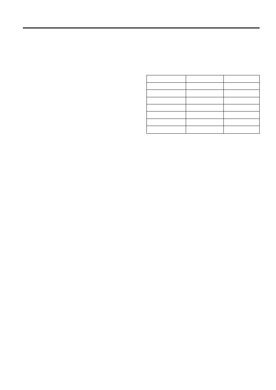
Gear
S1
S2
1st
ON
ON
2 n d
OFF
ON
3 r d
OFF
OFF
4 t h
ON
OFF
Reverse
OFF
OFF
Neutral
OFF
OFF
Park
OFF
OFF
•
Solenoid 6: S6 is a normally open ON/OFF solenoid
that sets the high/low level of line pressure. Solenoid
OFF gives high pressure.
•
Solenoid 7: S7 is a normally open ON/OFF solenoid
that controls the application of the converter clutch.
Solenoid ON activates the clutch.
Solenoid Logic for Static Gear States