SsangYong Rexton. Manual - part 393


  Index      SsangYong     SsangYong Rexton - service repair manual


Search            


Content   ..  391  392  393  394   ..


SsangYong Rexton. Manual - part 393


DIESEL ENGINE MECHANICAL  1B3-147

SSANGYONG  Y200

YAD1BJS0

YAD1BJT0

YAD1BJU0

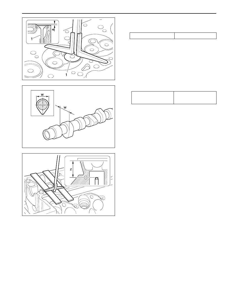
5. Insert the valve (1) into the valve guide according

to marking and measure amount by which the
valve arrears ‘a’.

7. Measure distance ‘z’ (cylinder head cover parting

surface - valve stem).

Arrears ‘a’

0.1 - 0.7 mm

38 ± 0.2 mm

or 37.6 ± 0.2 mm

Diameter ‘w’

6. Measure camshaft cam basic circle diameter (w).

SSANGYONG  Y200

1B3-148  DIESEL ENGINE MECHANICAL

YAD1BJK0

I Length of Valve

w Camshaft Cam Basic Circle Diameter

x Distance (Camshaft Basic Bore - Valve Stem)

y Half Camshaft Basic Bore Diameter
z Distance (CylinderHead Cover Parting Surface -

 Valve Stem)

8. Measure ‘x’ (Camshaft basic bore - valve stem).

‘ x ’   =   ‘ z ’   -   ‘ y ’

9. Determine the valve to be used.

(See ‘Matching valves’)

Example) Measured value ‘w’ = 38.2 mm

Measured value ‘z’ = 36.5 mm

V a l u e  ‘ y ’

= 15.5 mm

‘x’ = 36.5 - 15.5 = 21.0 mm

In the case of a camshaft cam basic circle
diameter  ‘w’ = 38.2 mm and a distance ‘x’  =
21.0 mm, the installed valve may be used.

DIESEL ENGINE MECHANICAL  1B3-149

SSANGYONG  Y200

YAD1BK00

Timing

*

At 2mm of valve lifting stroke.

1 Cylinder Head Cover
2 Bolt ........................................... 10 N•m (89 lb-in)
3 Gasket.................................................... Replace

4 Valve Tappet
5 Cylinder Head

Condition of camshaft

Intake valve

Open

ATDC 11.33°

ATDC 12°

Close

ABDC 17°

ABDC 18°

Exhaust valve

Open

BBDC 28°

BBDC 27°

CAMSHAFT TIMING TEST

Preceding Work: Removal of glow plug

Close

BTDC 15.25°

BTDC 14°

New

After approx. 20,000km

SSANGYONG  Y200

1B3-150  DIESEL ENGINE MECHANICAL

YAD1BK10

YAD1BK20

YAD1BC10

Tools Required

001 589 53 21 00

Dial Gauge

363 589 02 21 00

Dial Gauge Holder

366 589 00 21 05

Extension

Measurement Procedure

1. Remove the cylinder head cover.

2. Rotate the engine in the direction of engine rotation

until the intake valve of no. 1 cylinder is completely
closed. The cam lobe faces up (arrow).

Notice: Do not rotate the engine at the bolt of the
crankshaft sprocket. Do not rotate the engine in
the opposite direction of engine rotation. If do,
this will cause serious measuring errors.

3. Install the dial gauge holder 363 589 02 21 00 and

dial gauge 001 589 53 21 00 (7) with the extension
366 589 00 21 05 (8) to the cylinder head and
position the tracer pin (9) onto the valve tappet
(intake valve of cylinder no.1) with a preload of
min. 3mm.

Notice: The tracer pin should be positioned exactly
vertical.

4. Set the dial gauge to ‘0’.

5. Rotate the engine further in direction of rotation

until the dial gauge has moved back by 2 mm
(valve lift) to 1mm.

6. Check the timing.

Notice: If timing is out of standard, the camshaft
should be checked for wear and the timing chain
for stretch. If a difference of more than 4° exists,
the timing chain should be replaced.

7. Replace the gasket and install the cylinder head

cover.

Installation Notice

Tightening Torque

10 N•m (89 lb-in)

New

After approx.

ATDC 11.33°

ATDC 12°


Content   ..  391  392  393  394   ..